The Seven-Segment Led
From: www.play-hookey.com Date: 2007-9-14
Introduction
One common requirement for many different digital devices is a visual numeric display. Individual LEDs can of course display the binary states of a set of latches or flip-flops. However, we're far more used to thinking and dealing with decimal numbers. To this end, we want a display of some kind that can clearly represent decimal numbers without any requirement of translating binary to decimal or any other format.
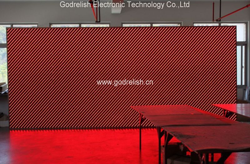
One possibility is a matrix of 28 LEDs in a 7×4 array. We can then light up selected LEDs in the pattern required for whatever character we want. Indeed, an expanded version of this is used in many ways, for fancy displays. However, if all we want to display is numbers, this becomes a bit expensive. A much better way is to arrange the minimum possible number of LEDs in such a way as to represent only numbers in a simple fashion.
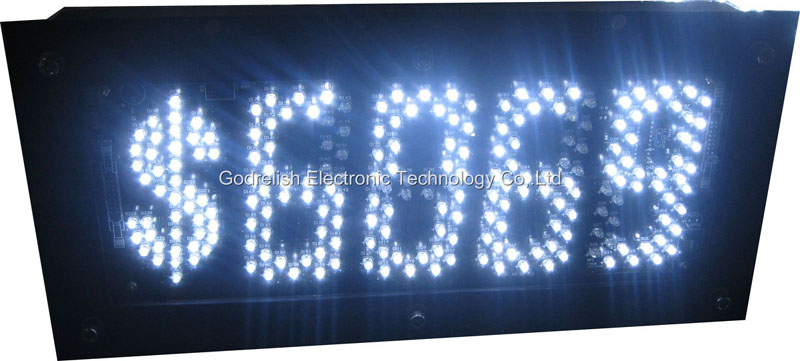
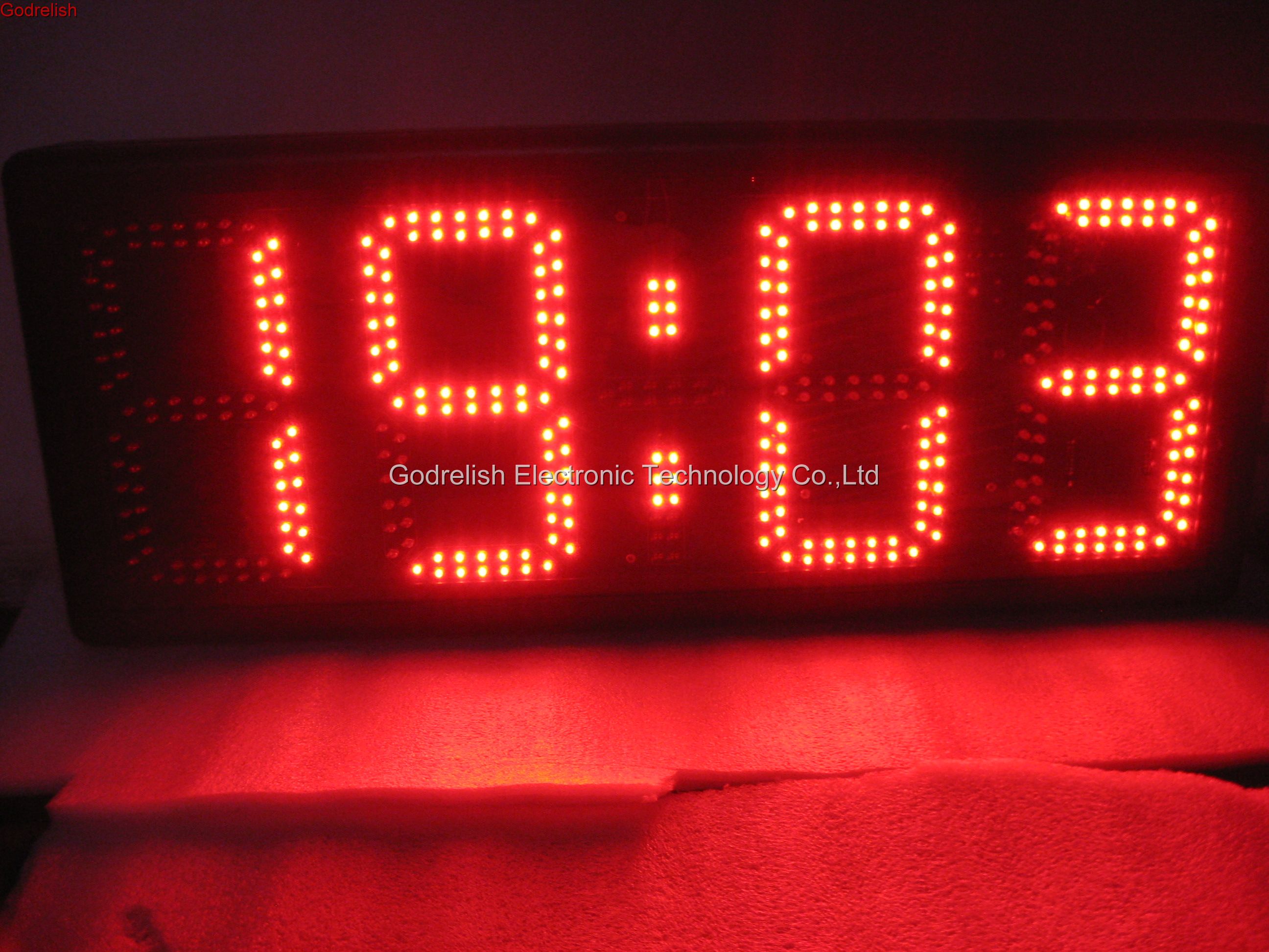
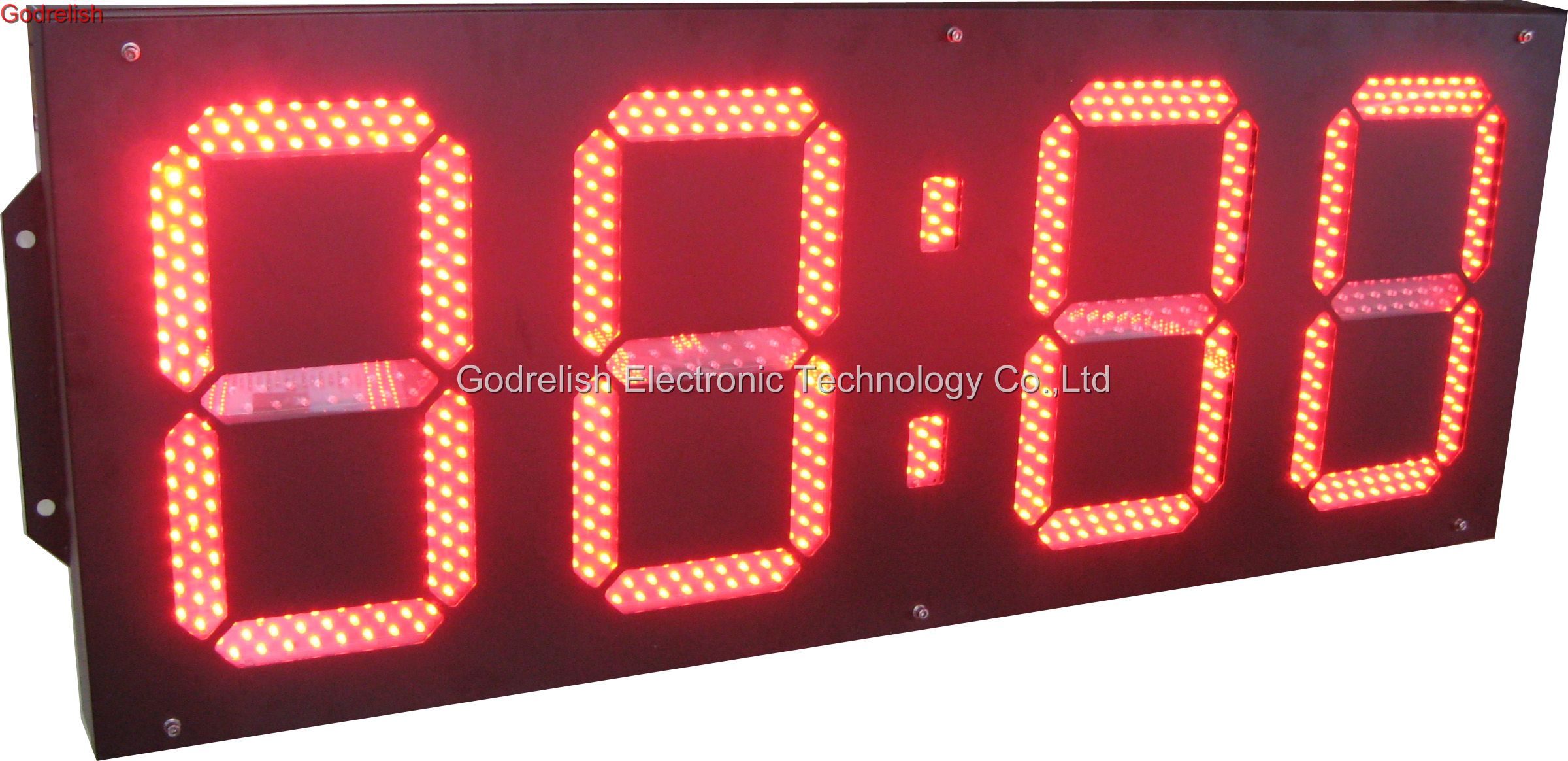
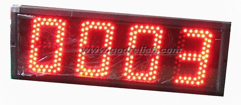
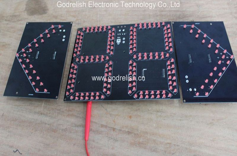
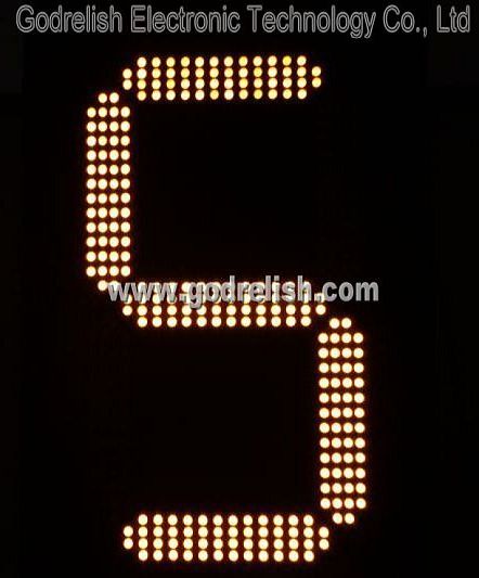
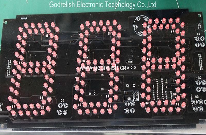
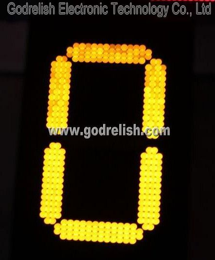
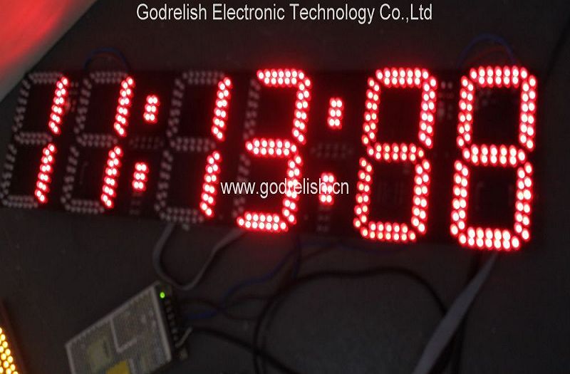
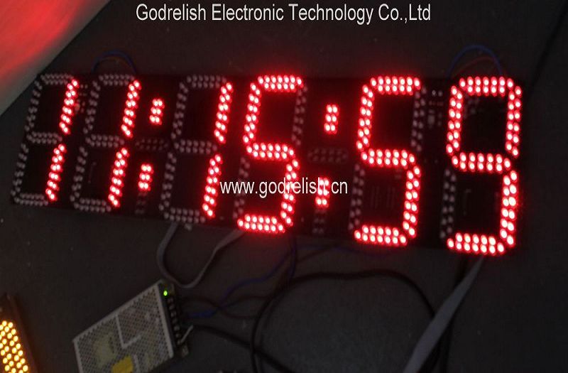
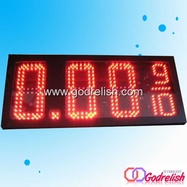
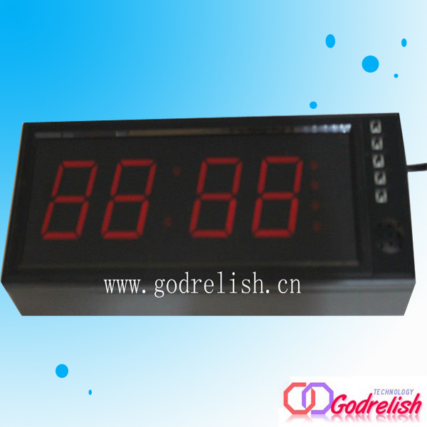
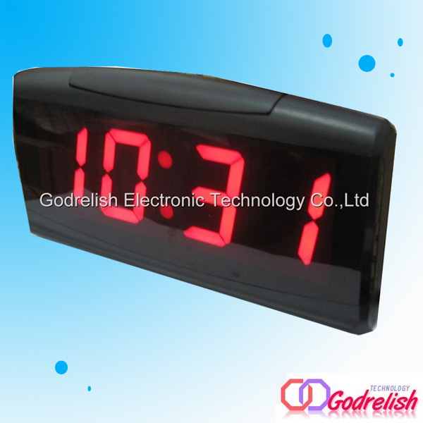
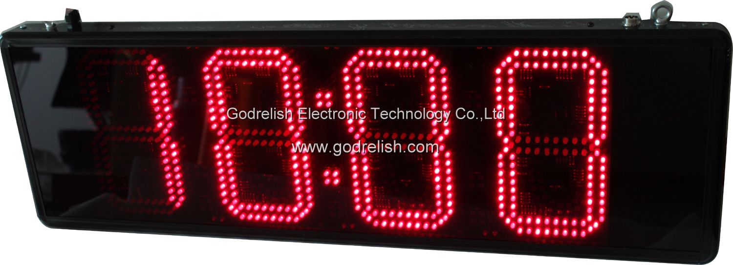
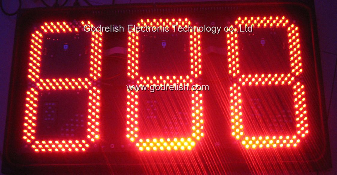
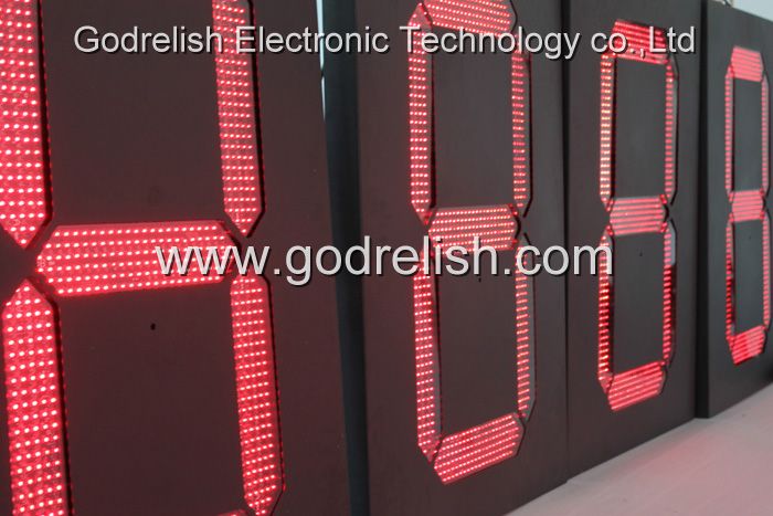
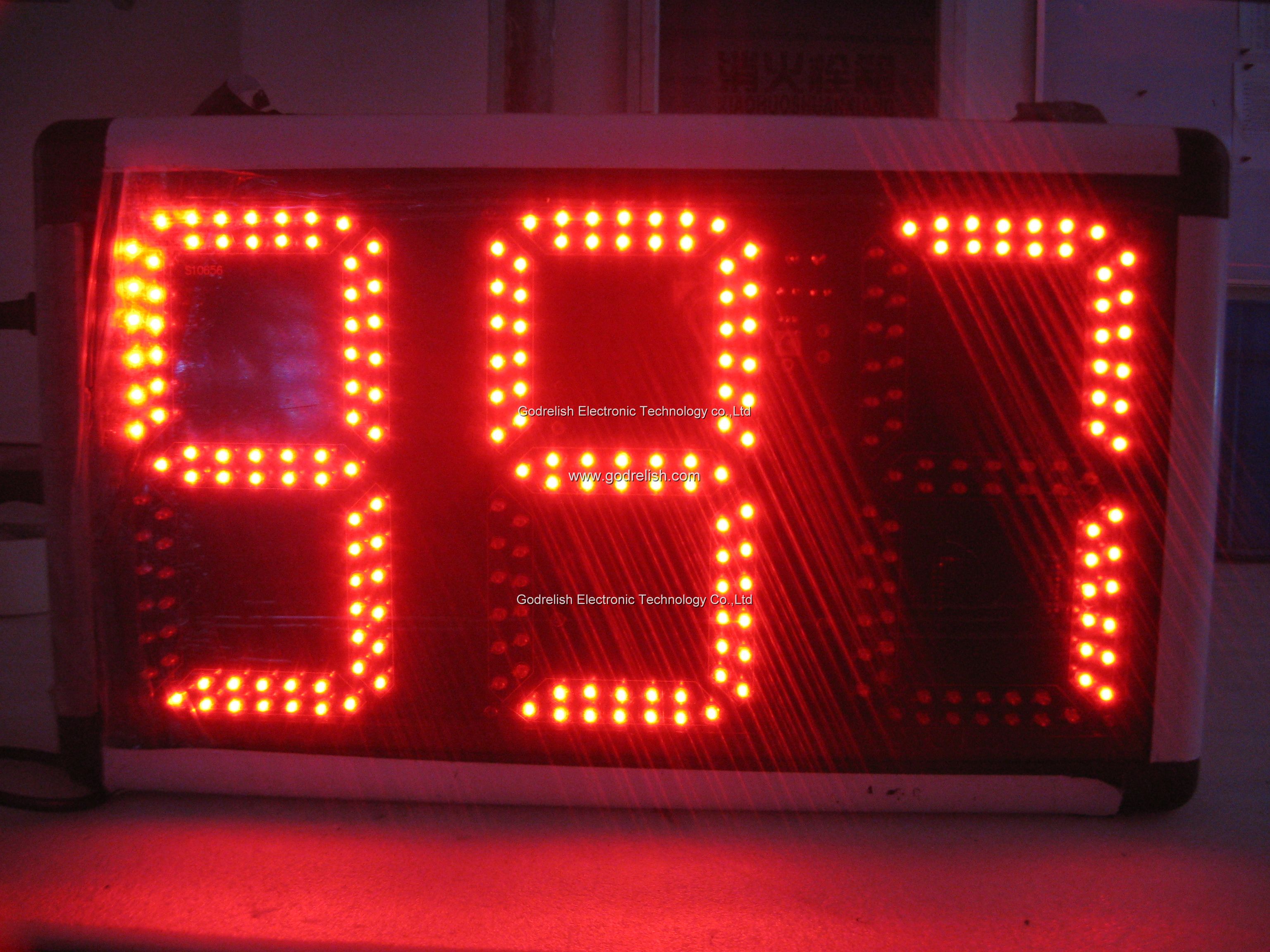
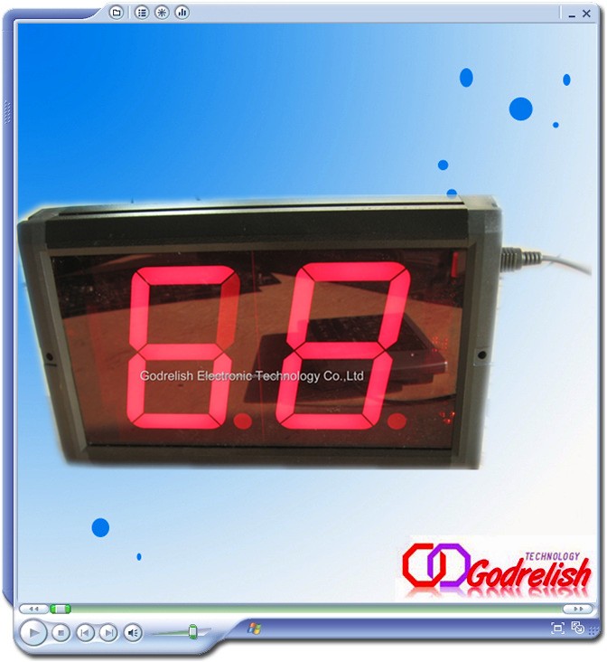
This requires just seven LEDs (plus an eighth one for the decimal point, if that is needed). A common technique is to use a shaped piece of translucent plastic to operate as a specialized optical fiber, to distribute the light from the LED evenly over a fixed bar shape. The seven bars are laid out as a squared-off figure "8". The result is known as a seven-segment LED.
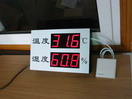
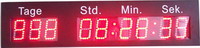
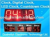
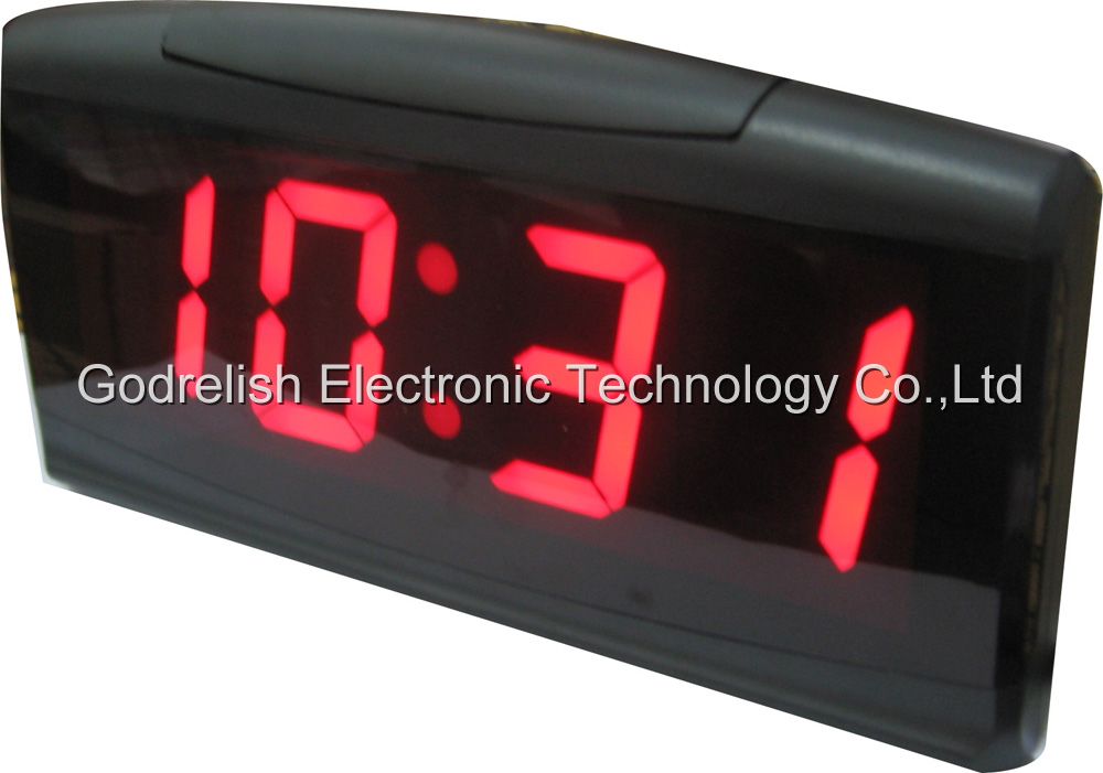
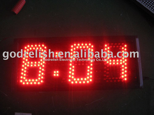
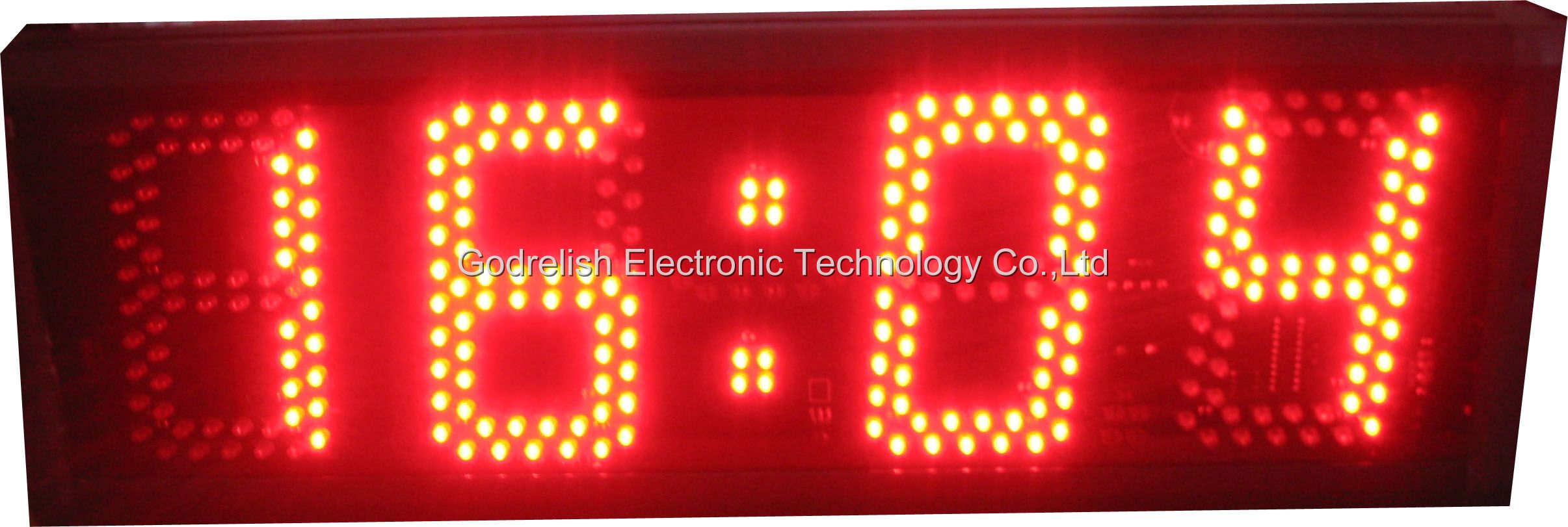
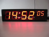
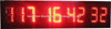
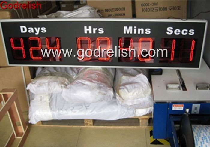
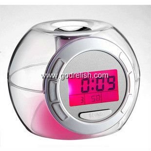
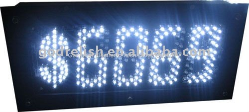
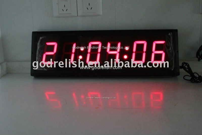
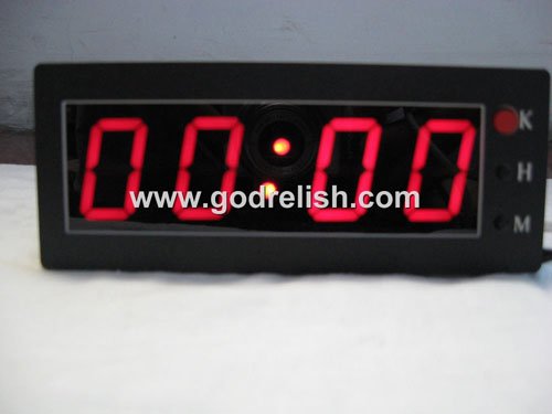
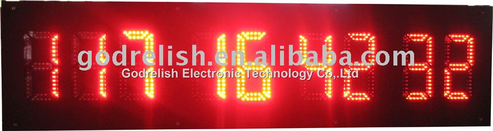
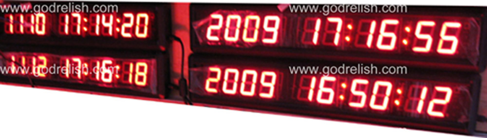
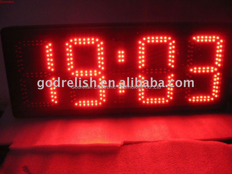
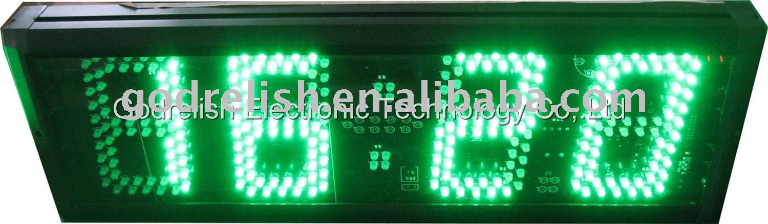
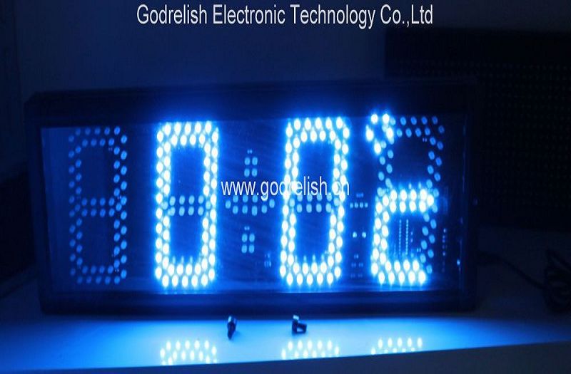
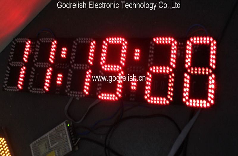
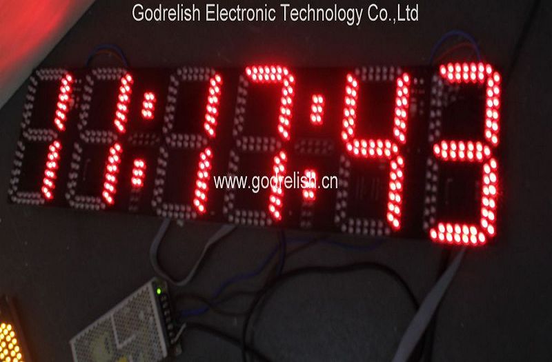
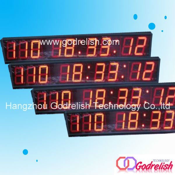
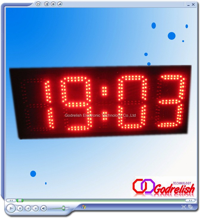
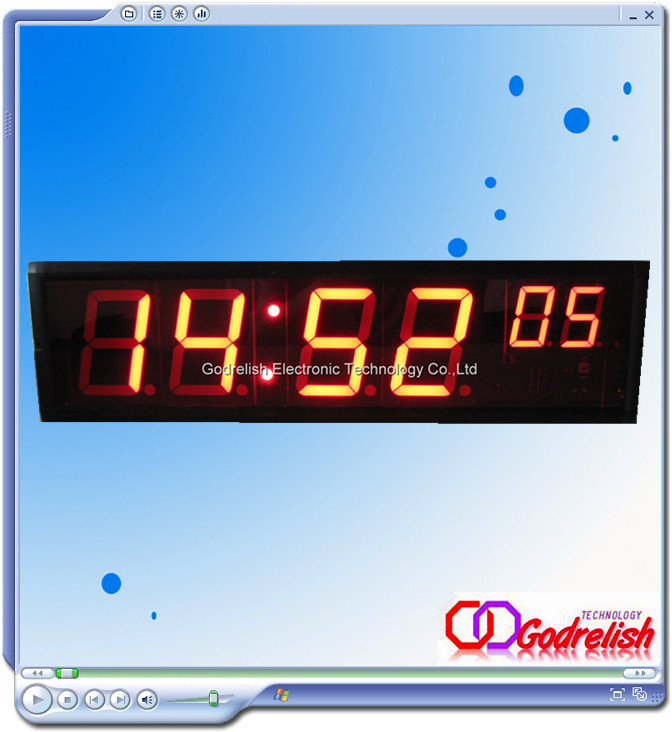
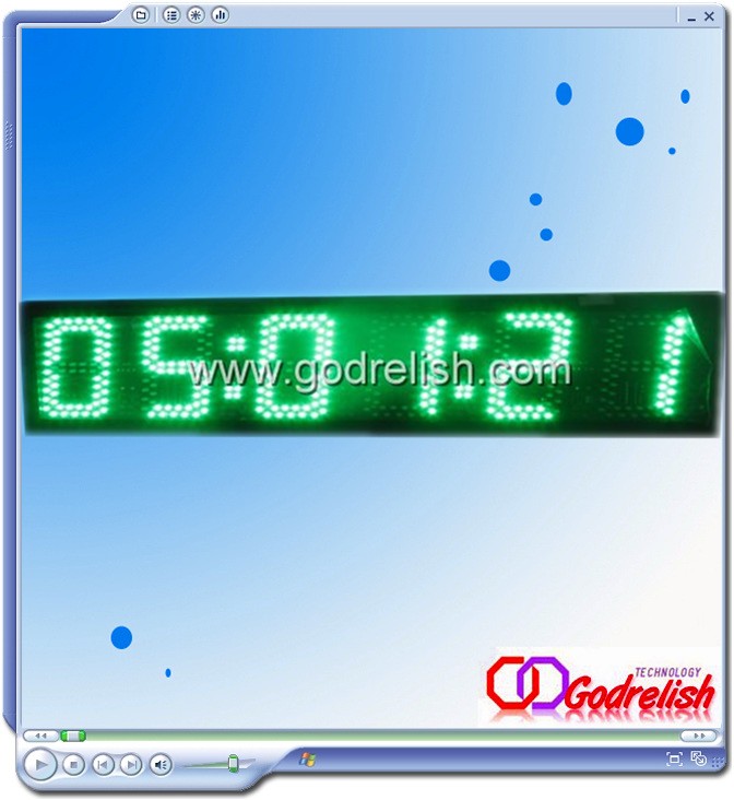
We've all seen seven-segment displays in a wide range of applications. Clocks, watches, digital instruments, and many household appliances already have such displays and so on.In this experiment, we'll look at what they are and how they can display any of the ten decimal digits 0-9 on demand.
Seven-Segment Display Layout
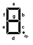
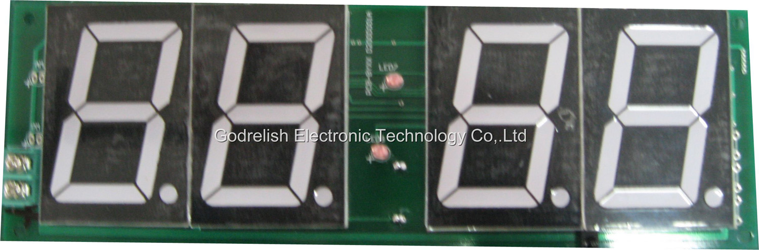
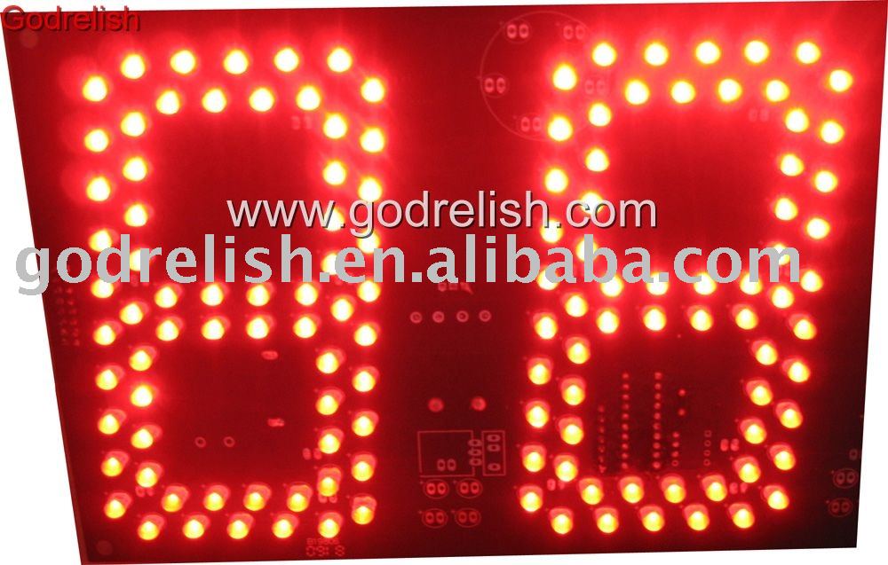
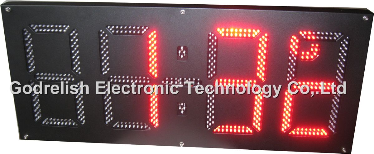
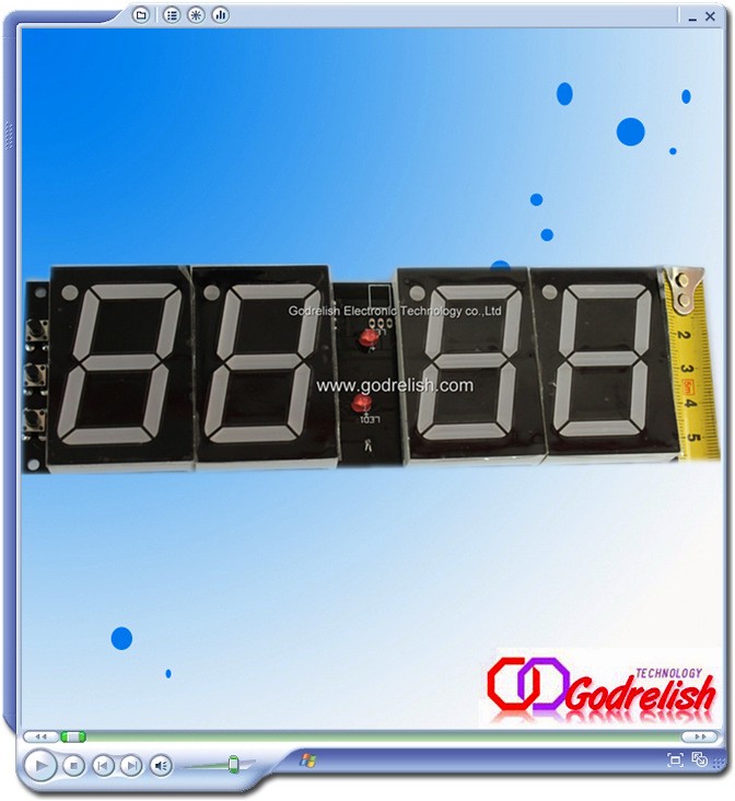
The illustration to the right shows the basic layout of the segments in a seven-segment display. The segments themselves are identified with lower-case letters "a" through "g," with segment "a" at the top and then counting clockwise. Segment "g" is the center bar.
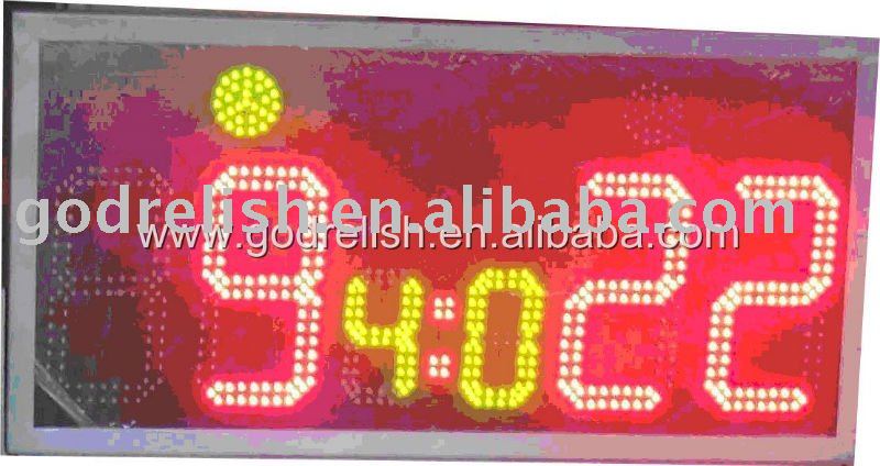
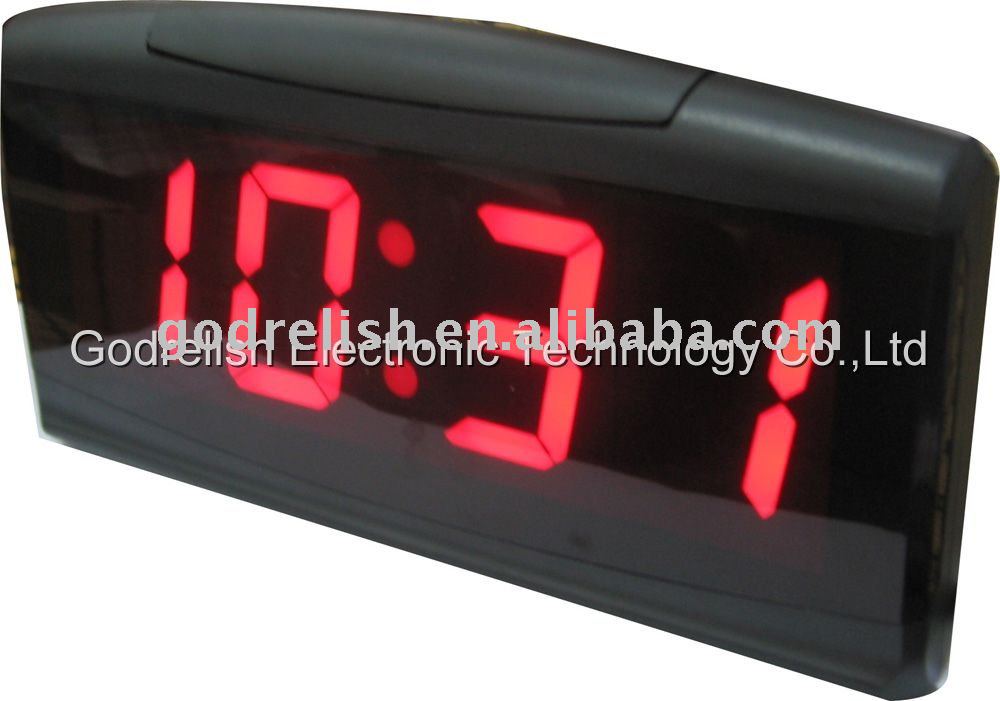
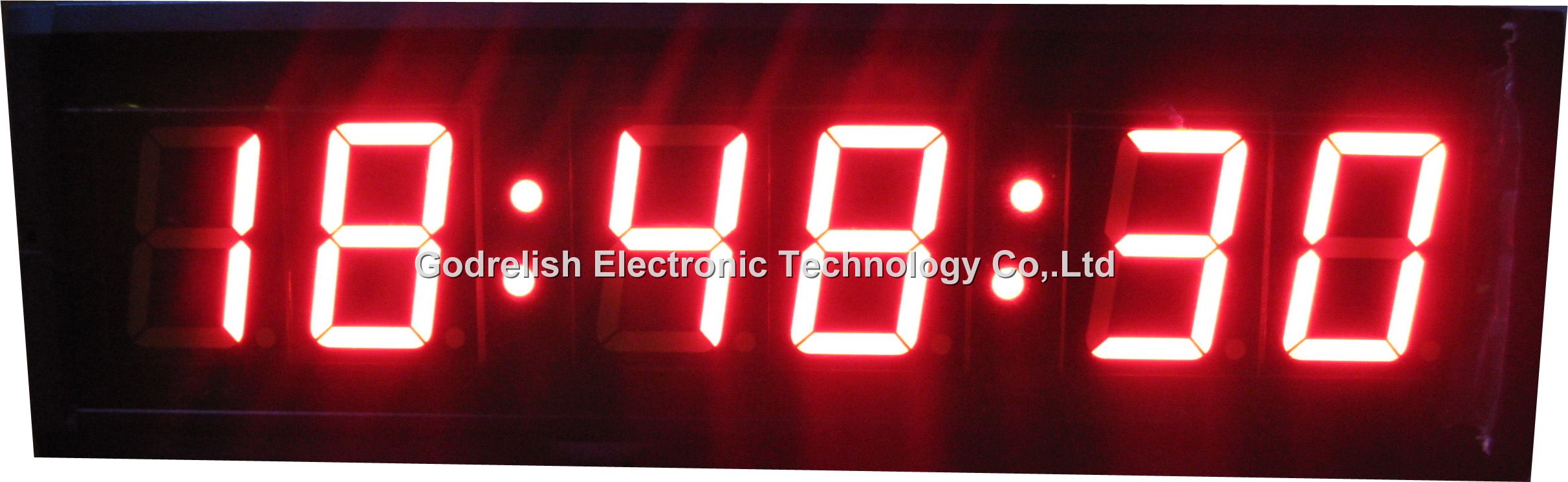
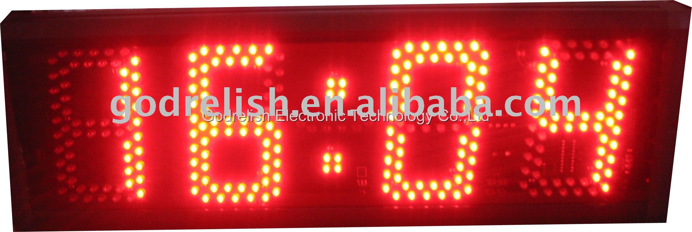
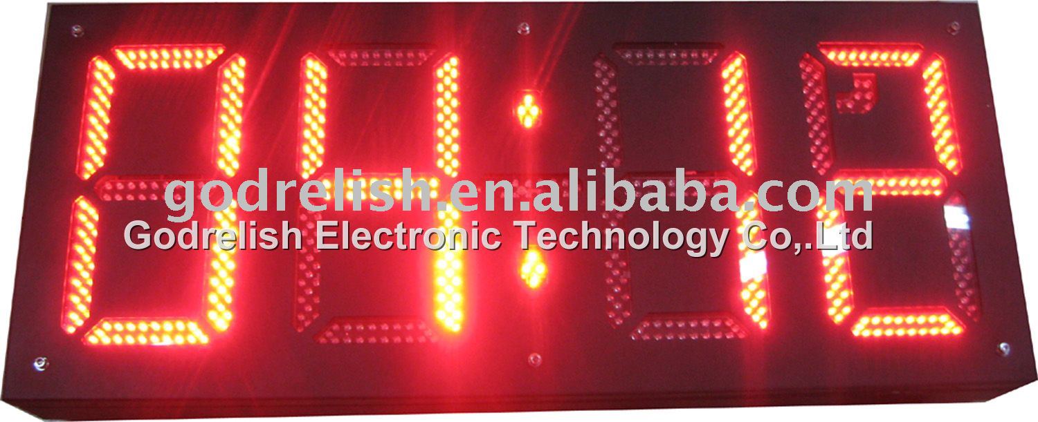
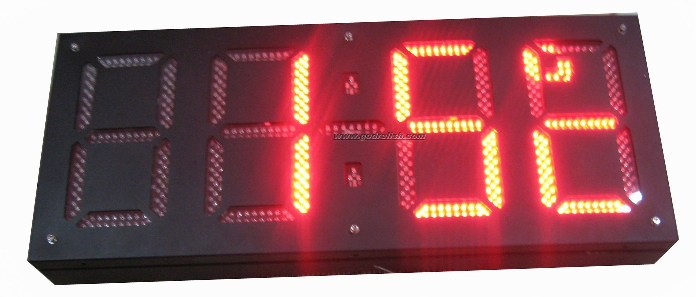
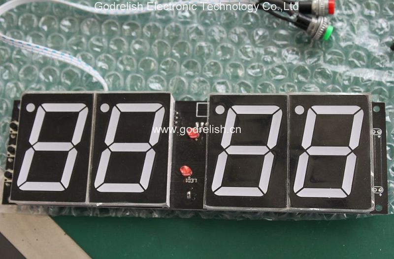
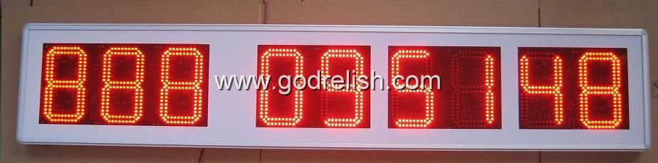
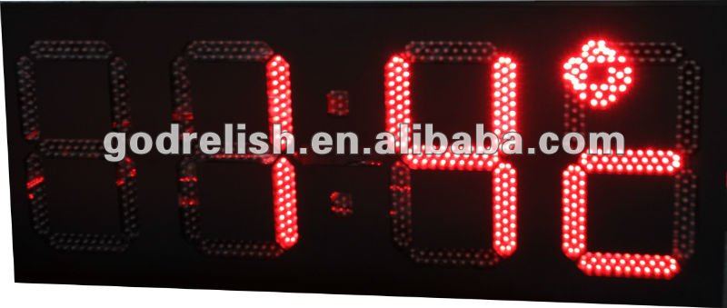
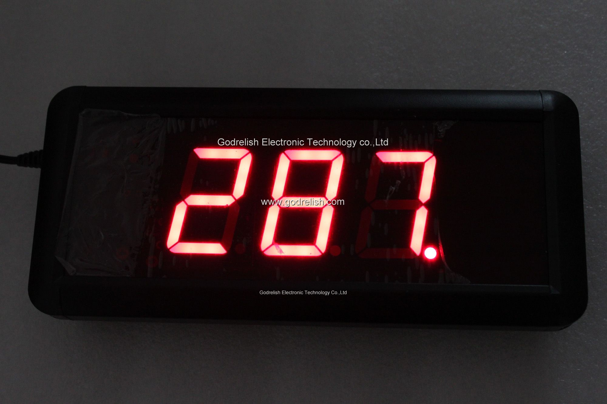
Most seven-segment digits also include a decimal point ("dp"), and some also include an extra triangle to turn the decimal point into a comma. This improves readability of large numbers on a calculator, for example. The decimal point is shown here on the right, but some display units put it on the left, or have a decimal point on each side.
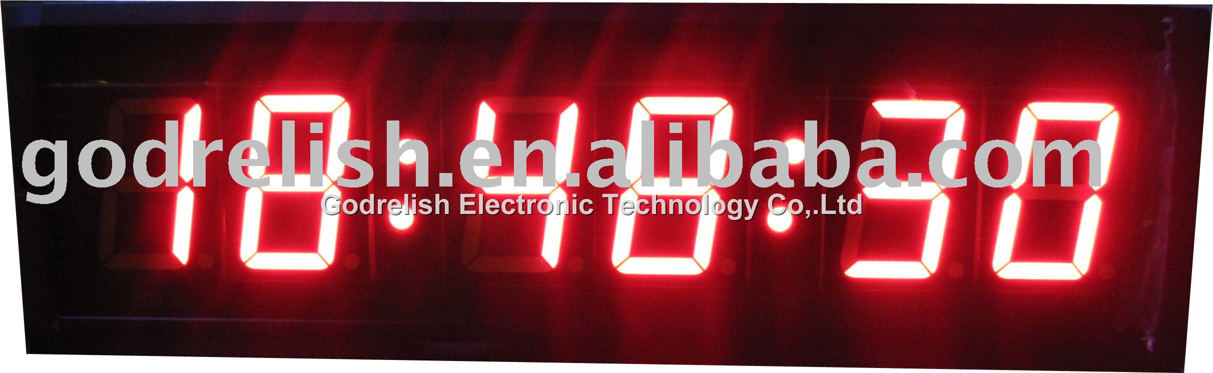
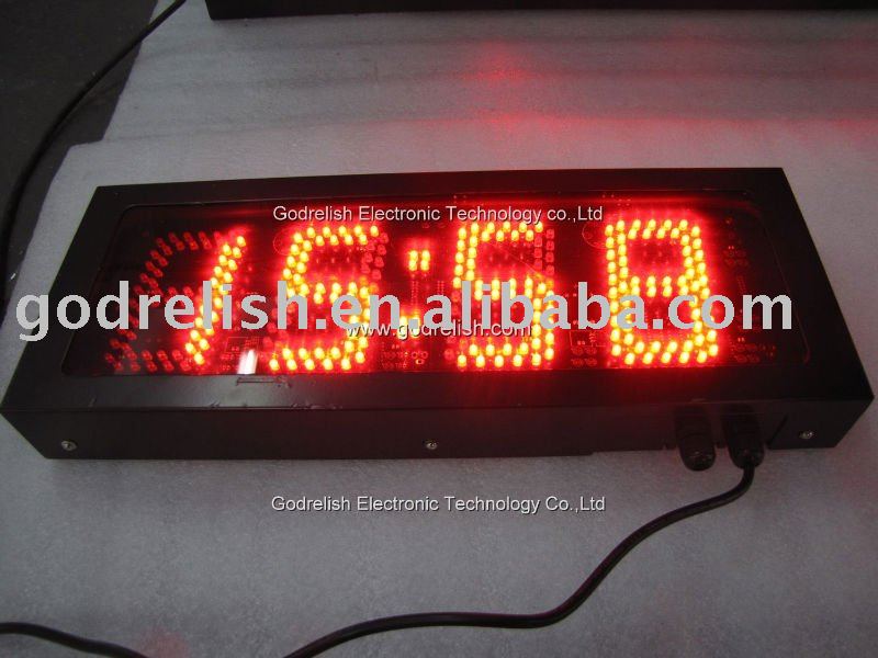
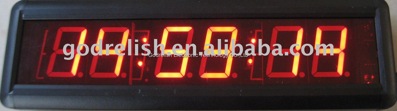
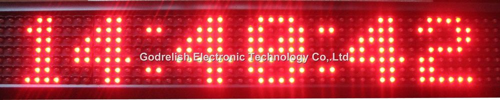
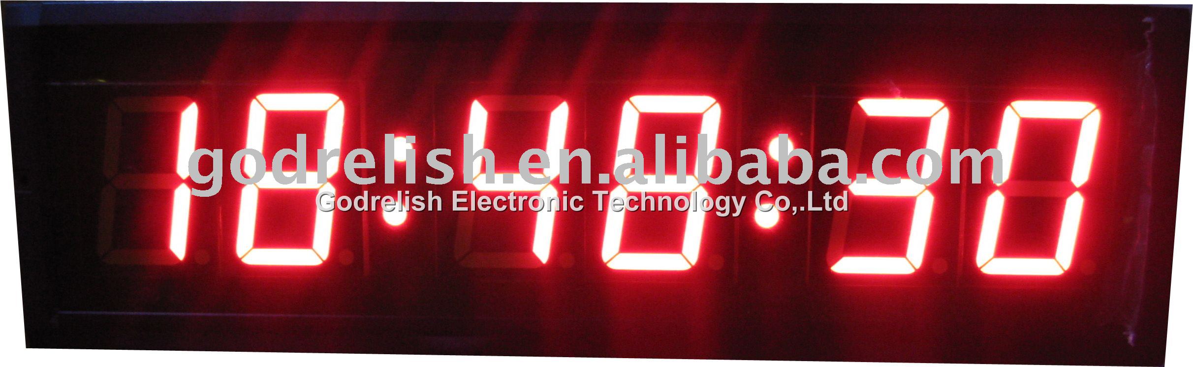
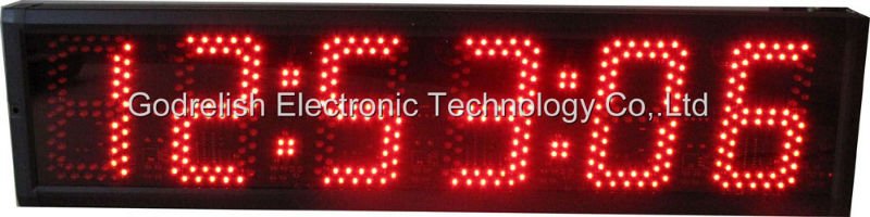
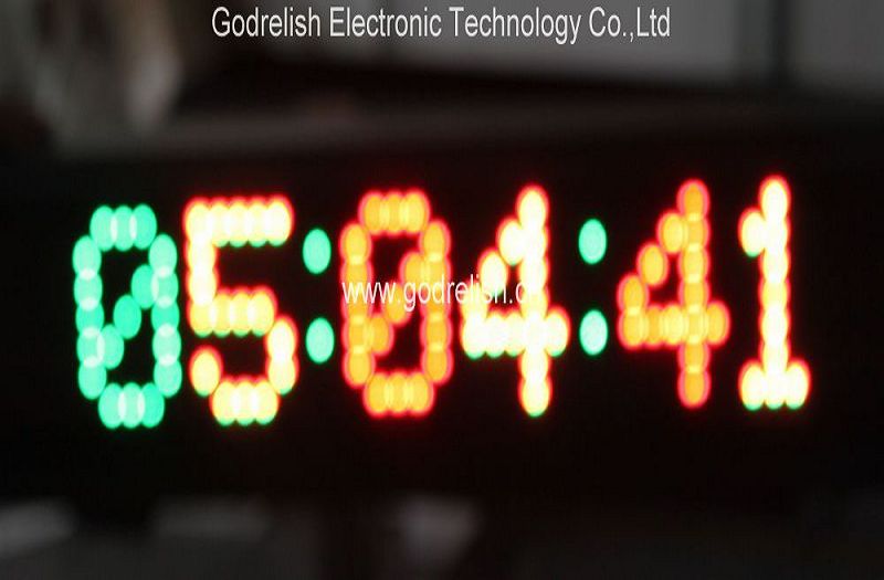
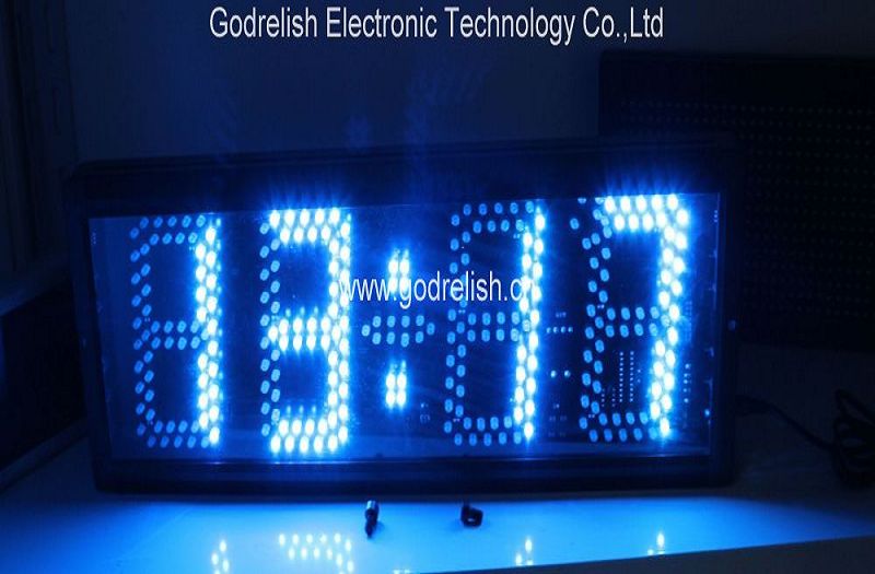
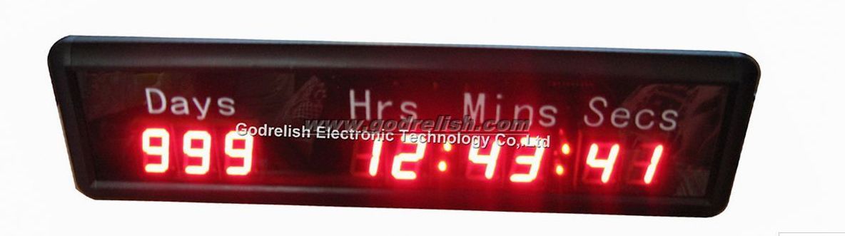
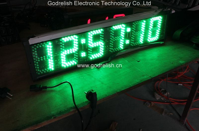
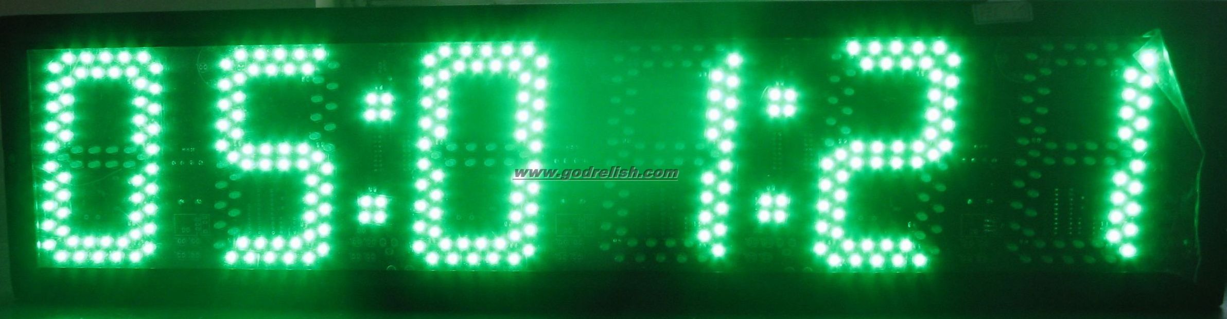
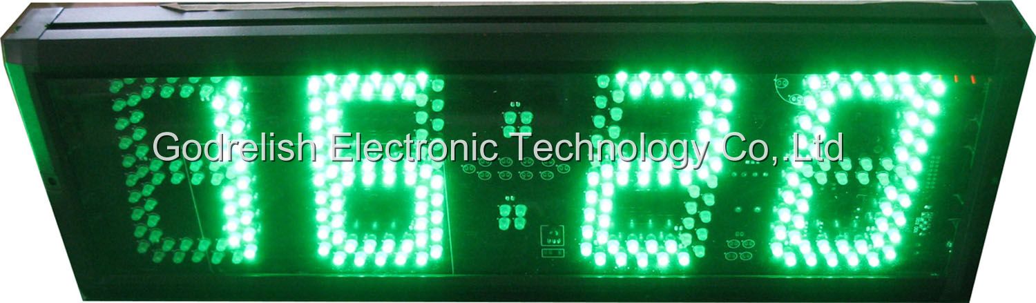
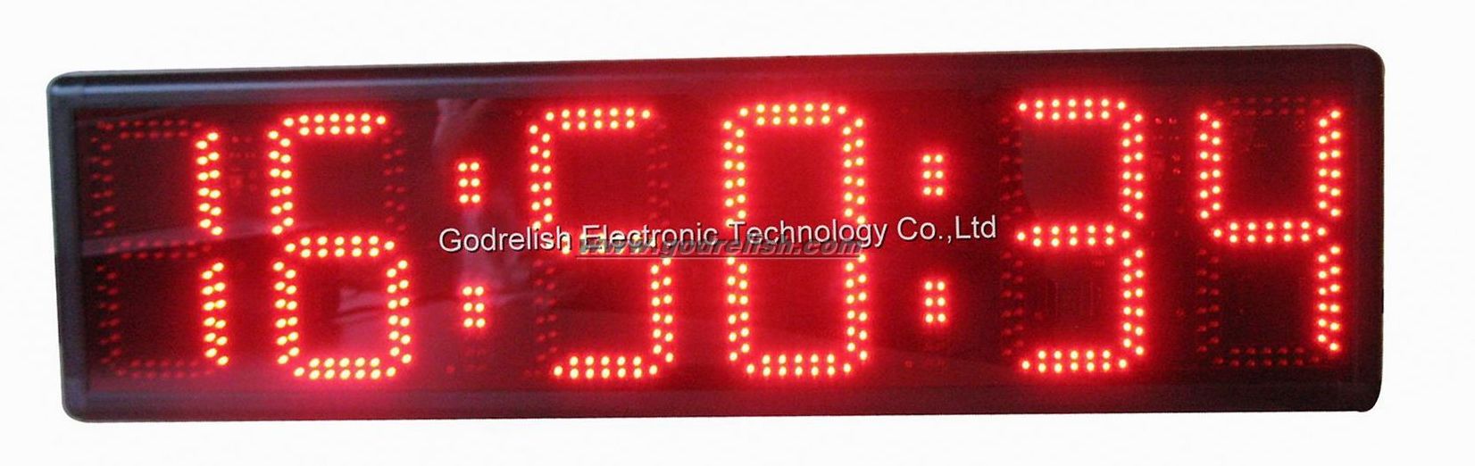
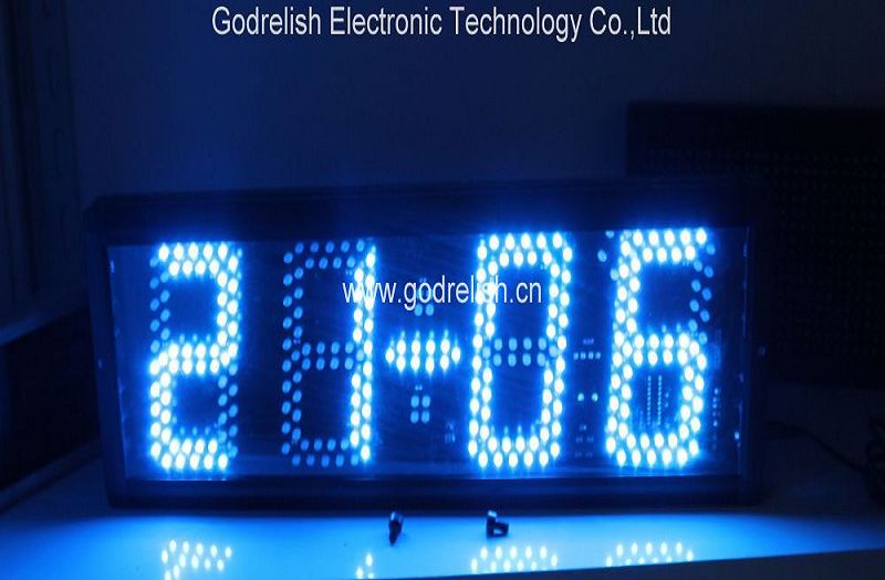
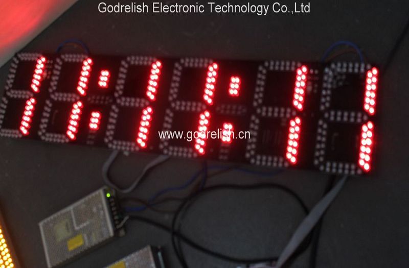
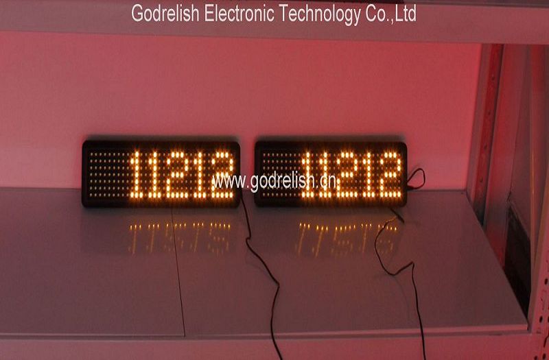
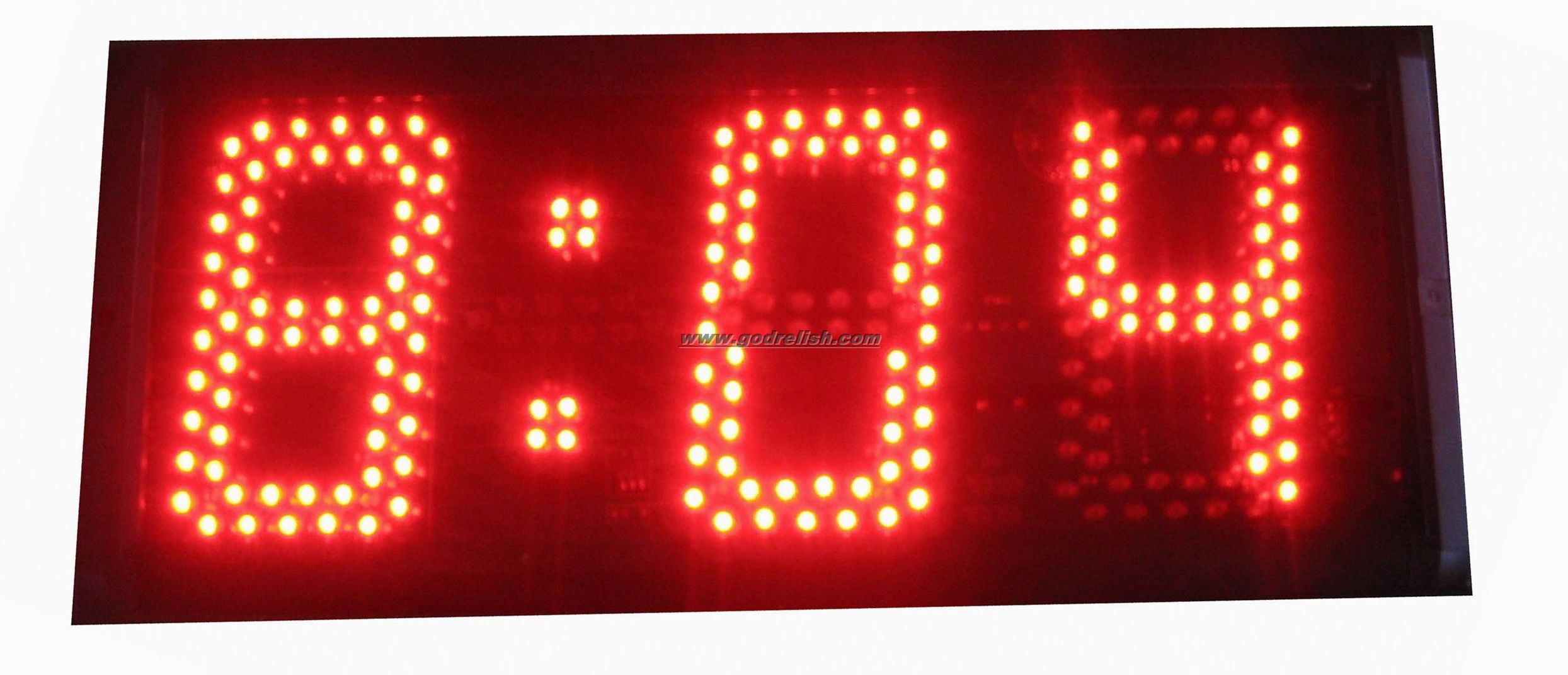
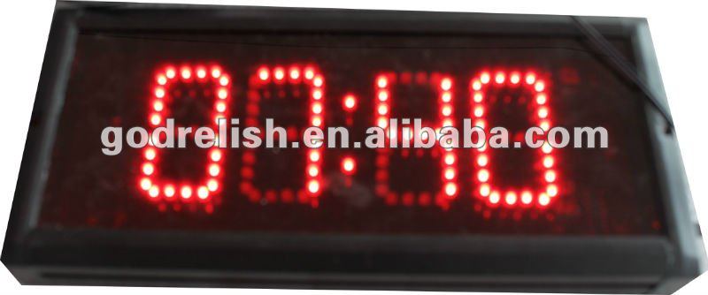
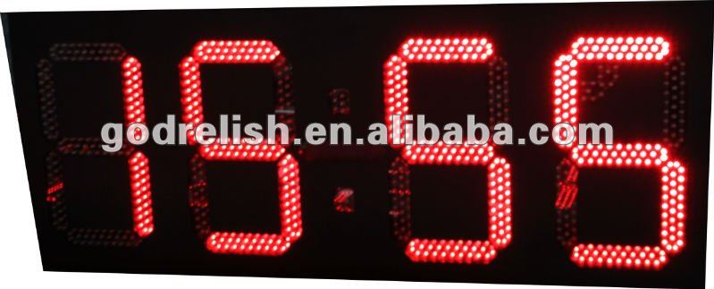
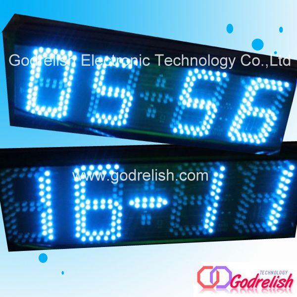
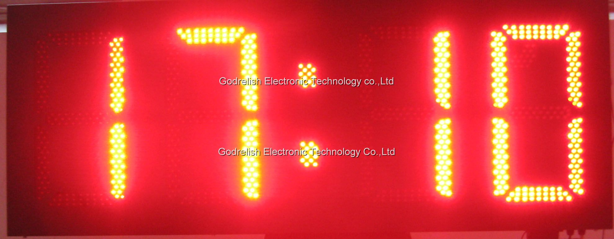
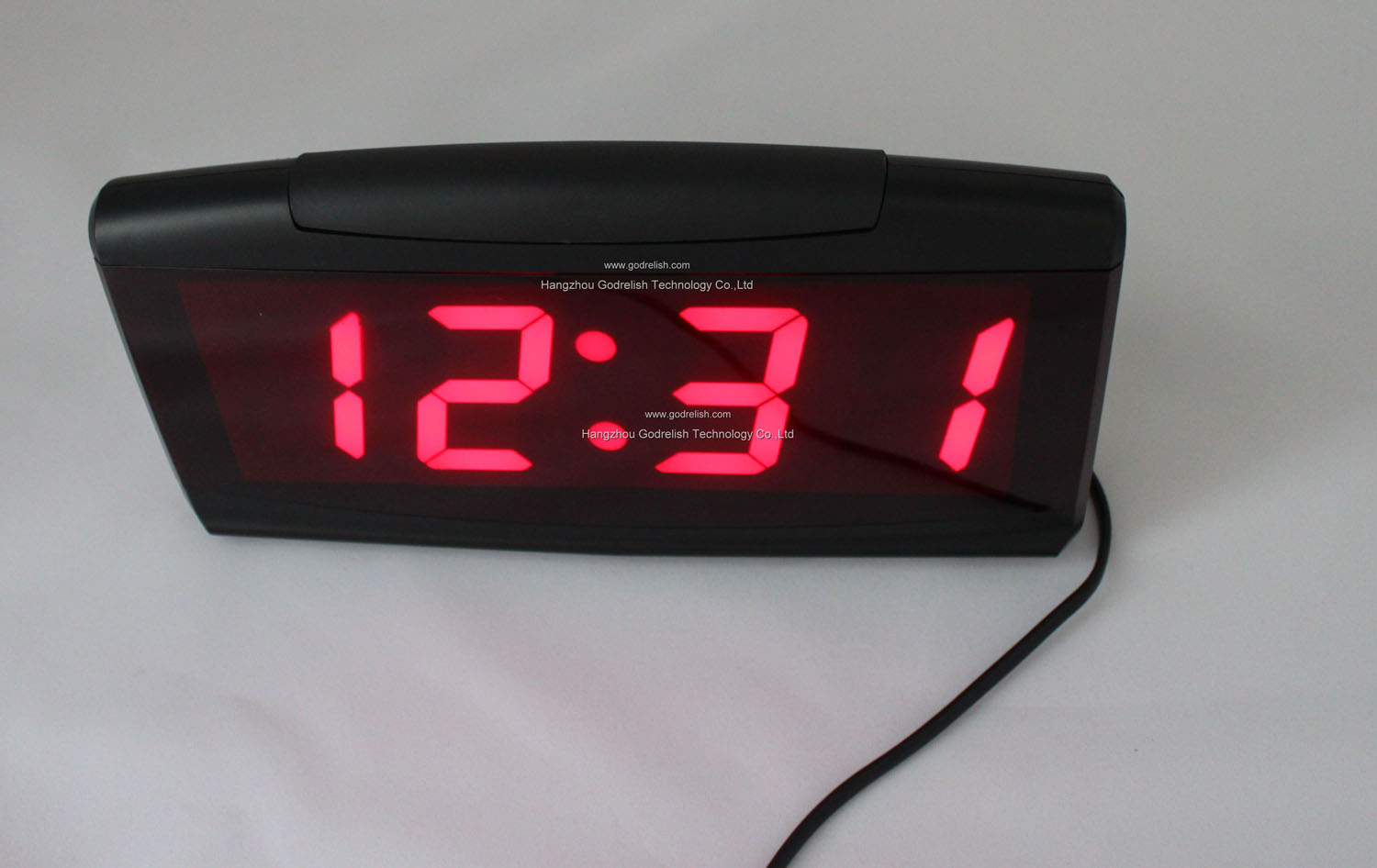
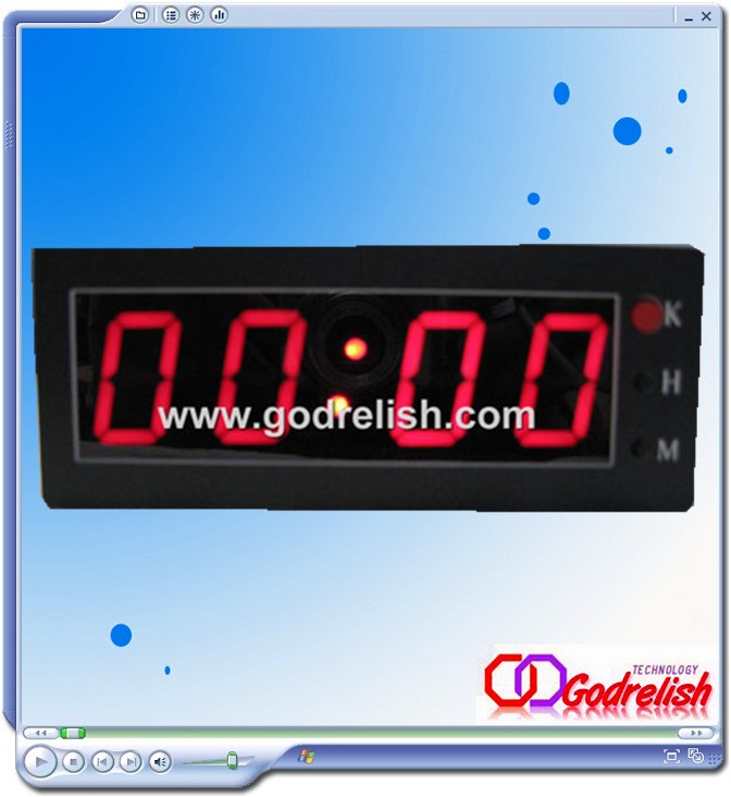
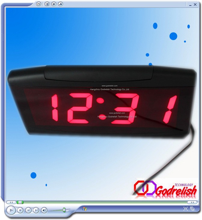
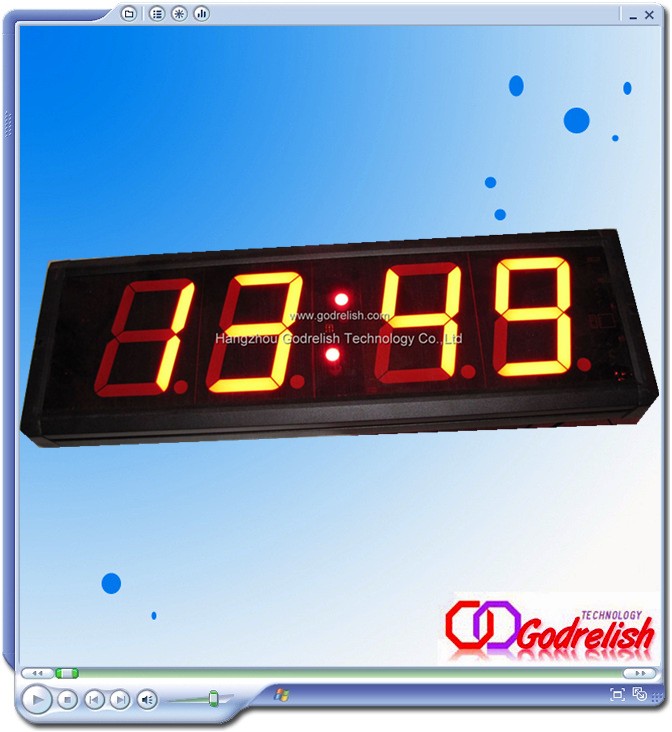
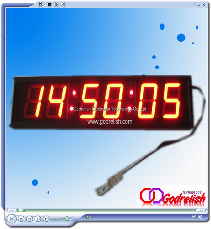
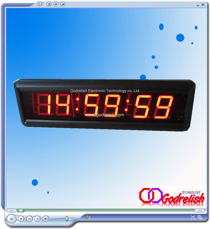
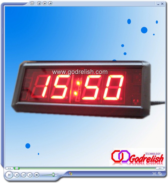
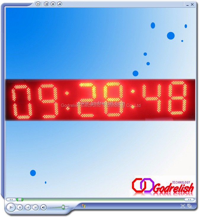
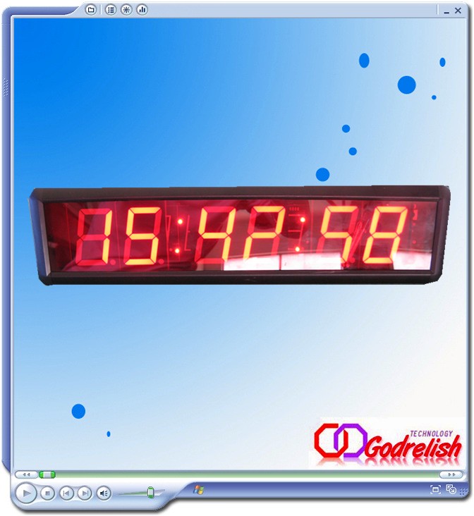
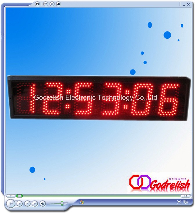
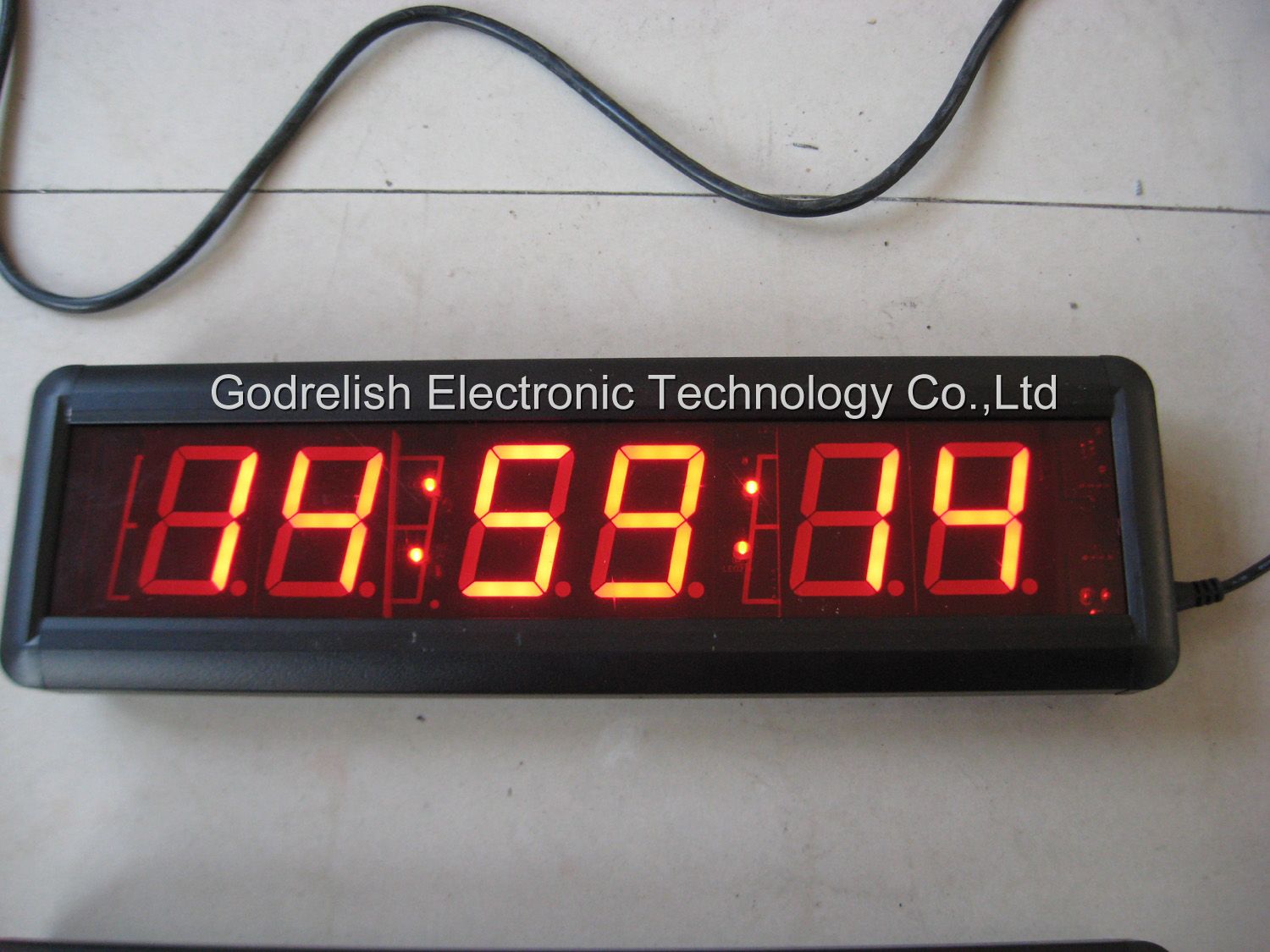
In addition, most displays are actually slanted a bit, making them look as if they were in italics. This arrangement allows us to turn one digit upside down and place it next to another, so that the two decimal points look like a colon between the two digits. The technique is commonly used in LED clock displays.
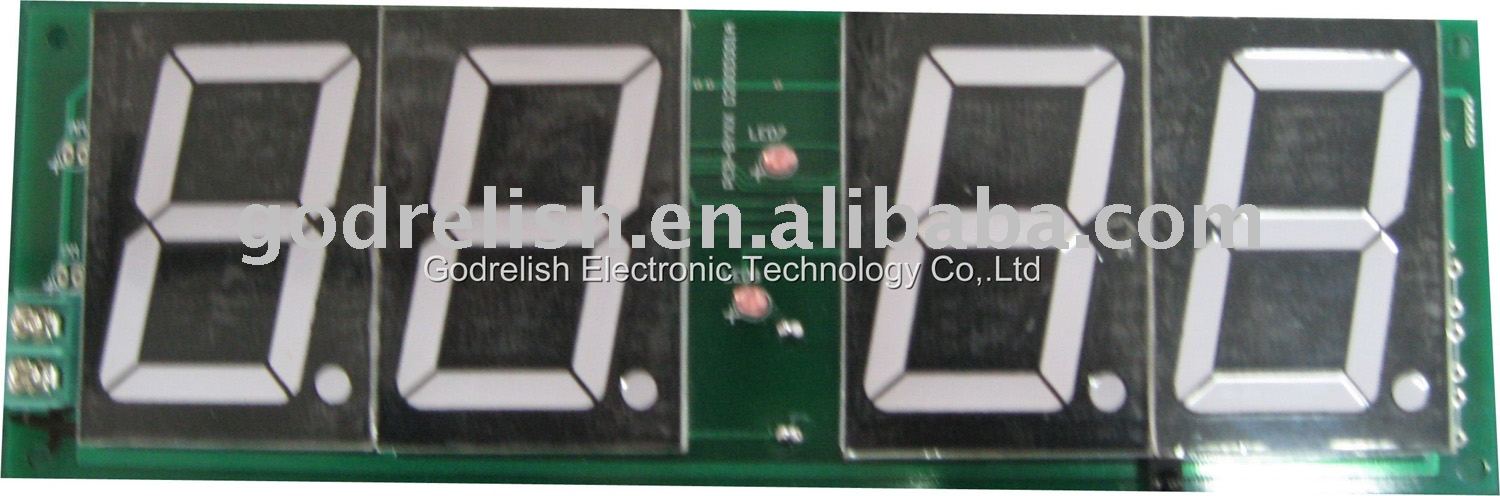
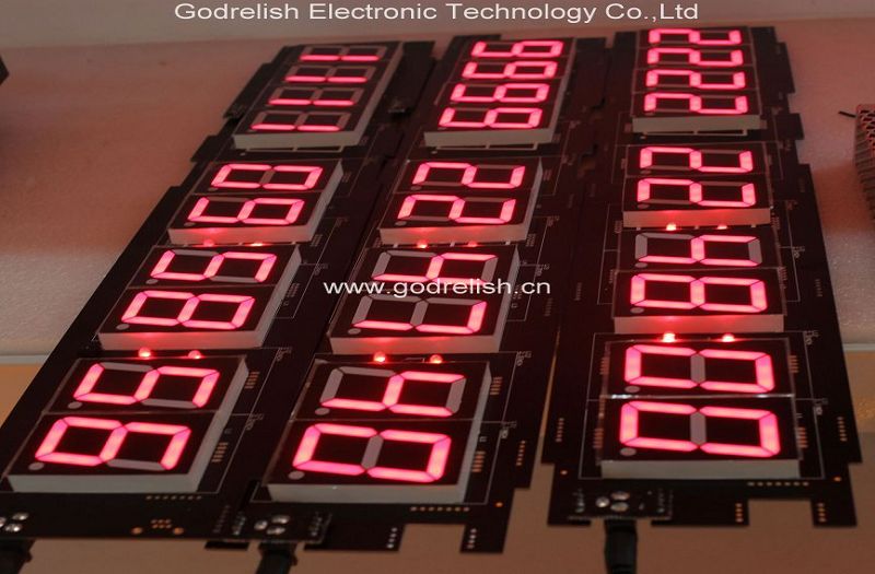
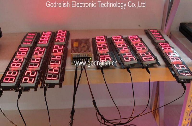
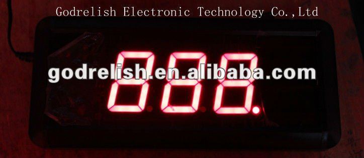
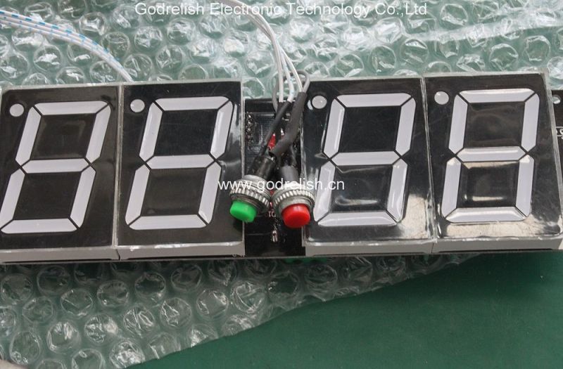
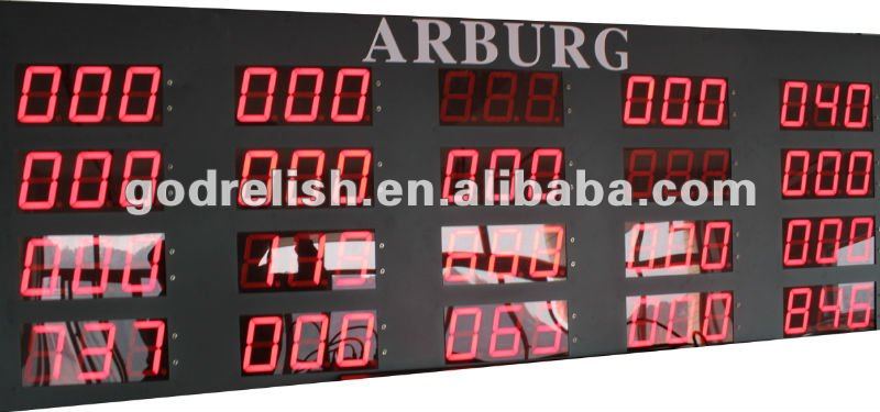
Seven-segment displays can be packaged in a number of ways. Three typical packages are shown above. On the left we see three small digits in a single 12-pin DIP package. The individual digits are very small, so a clear plastic bubble is molded over each digit to act as a magnifying lens. The sides of the end bubbles are flattened so that additional packages of this type can be placed end-to-end to create a display of as many digits as may be needed.
The second package is essentially a 14-pin DIP designed to be installed vertically. Note that for this particular device, the decimal point is on the left. This is not true of all seven-segment displays in this type of package.
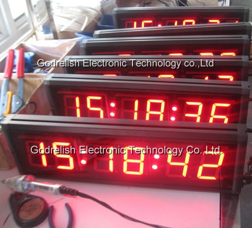
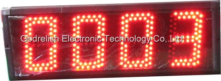
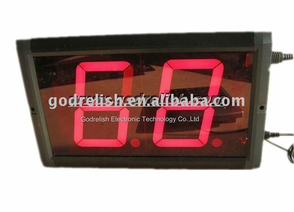
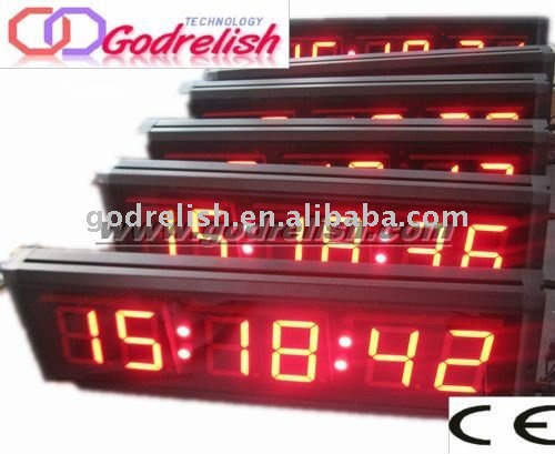
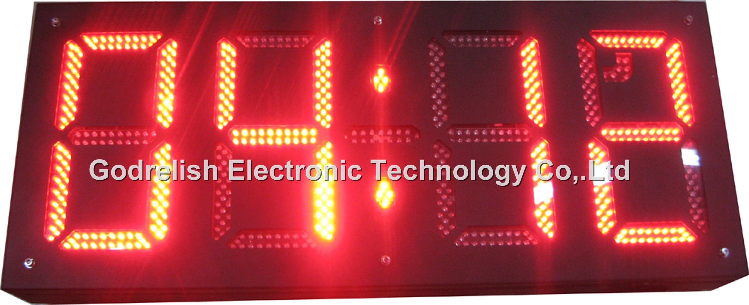
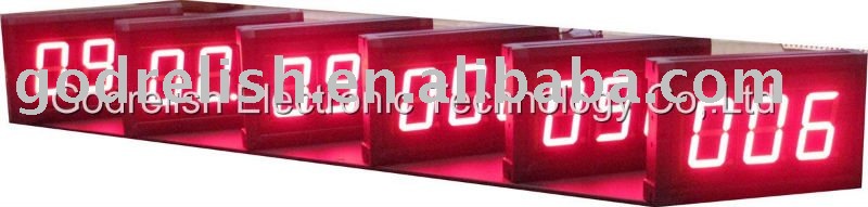
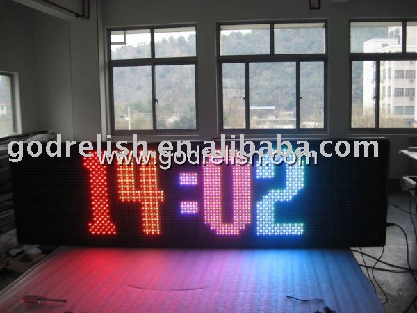
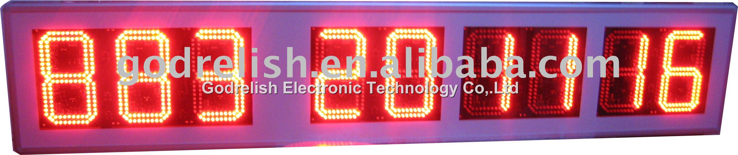
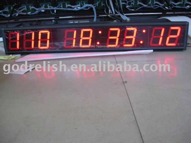
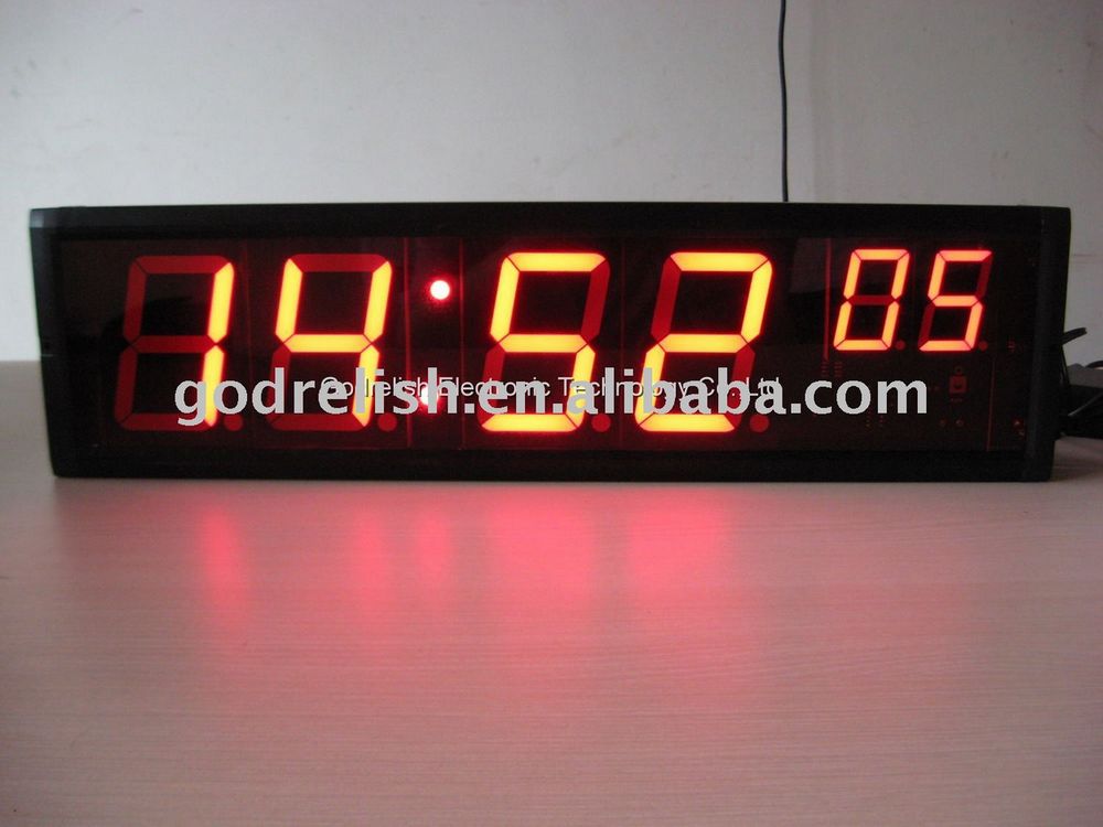
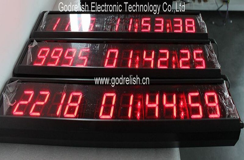
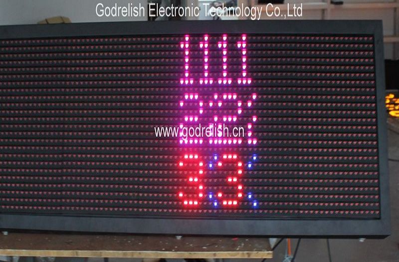
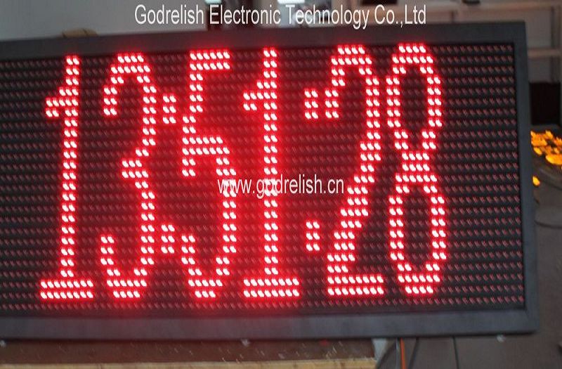
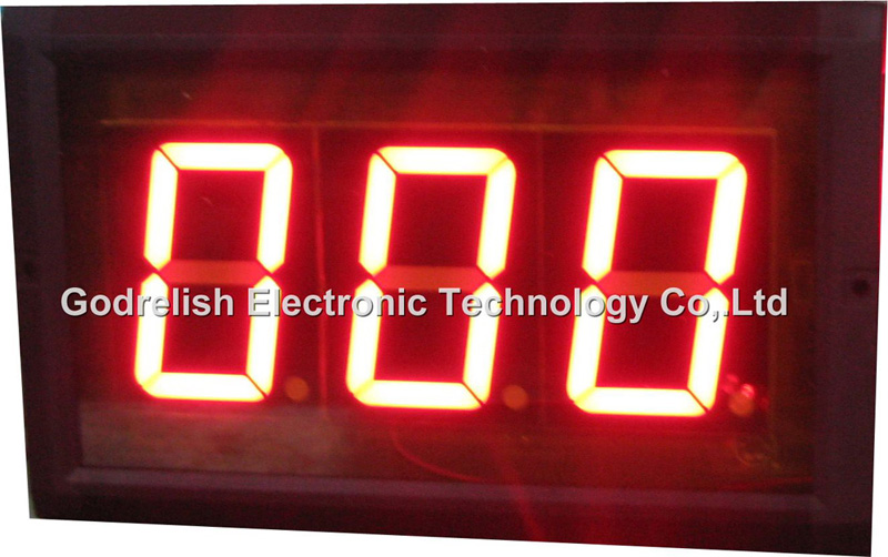
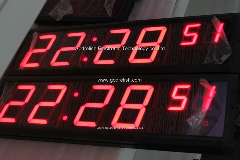
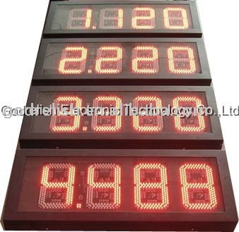
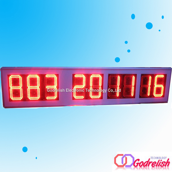
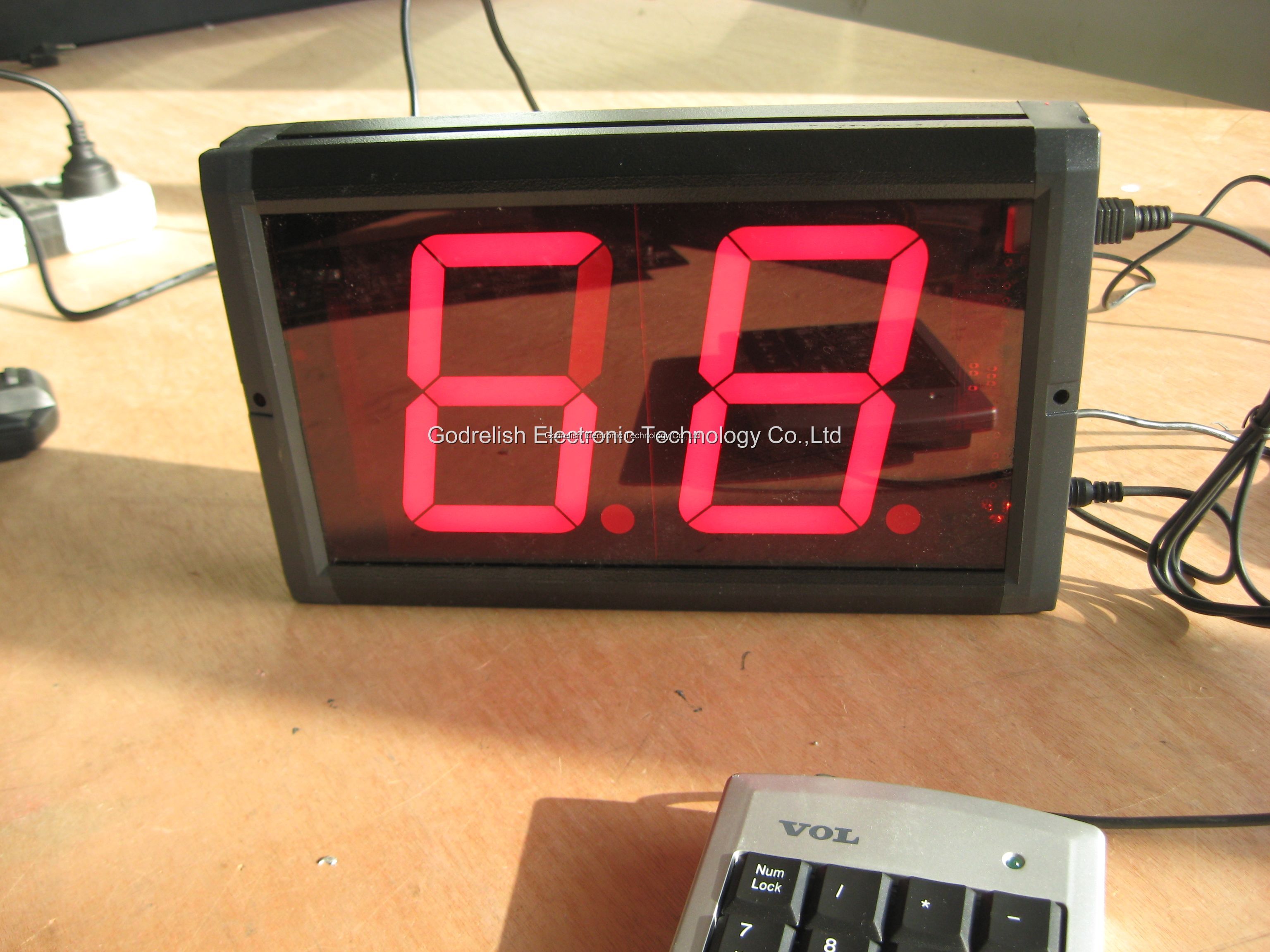
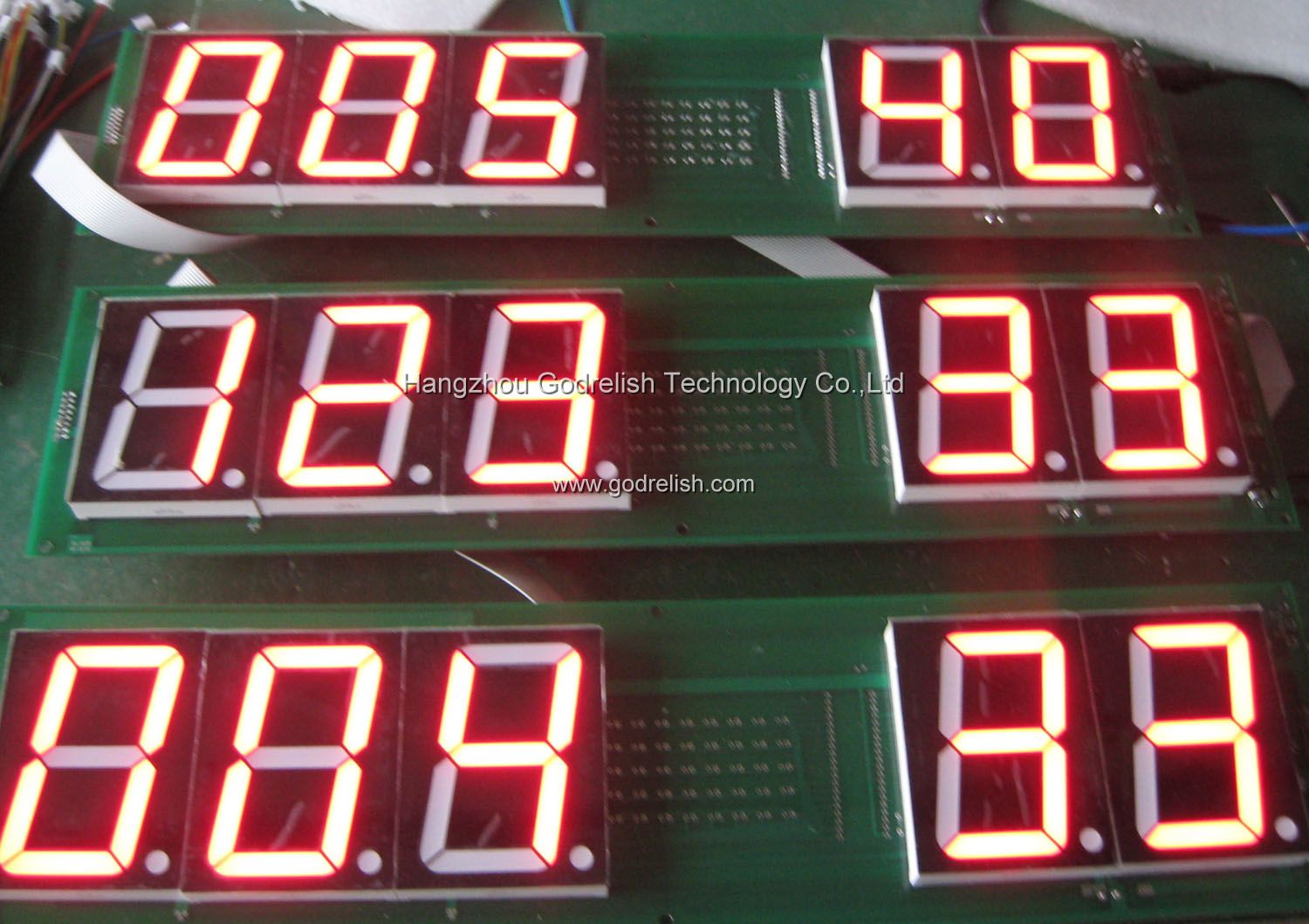
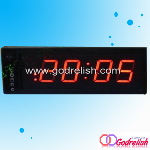
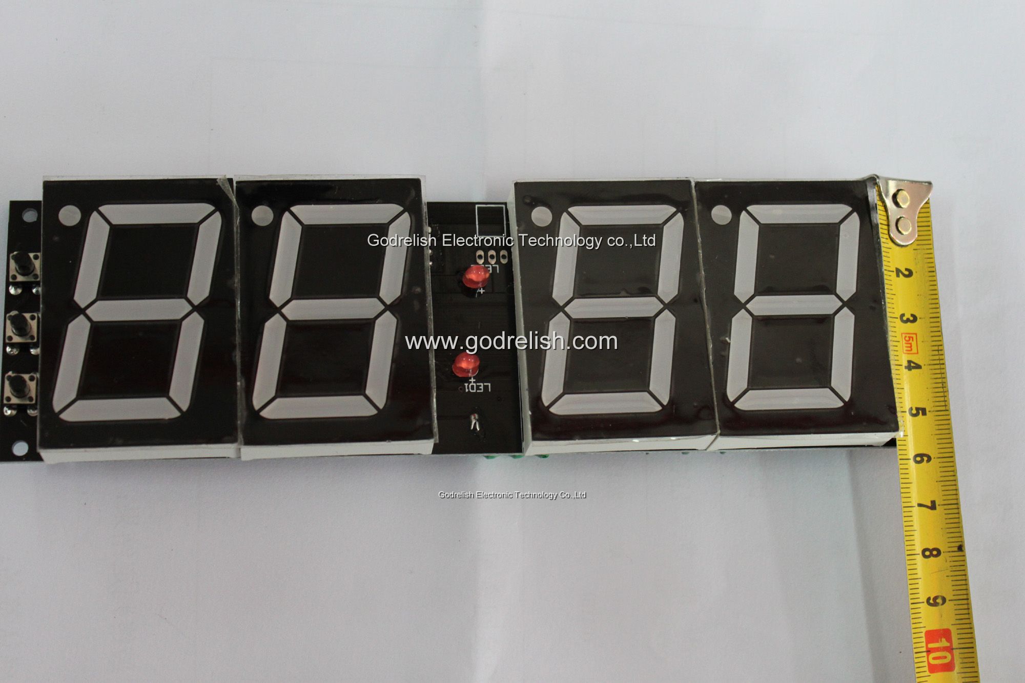
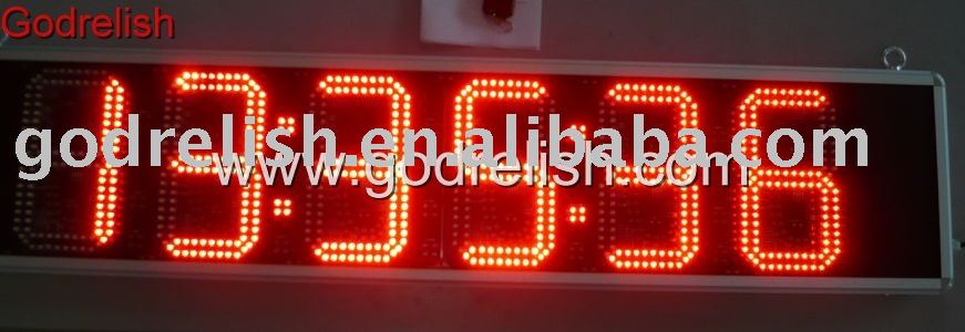
One limitation of the DIP package is that it cannot support larger digits. To get larger displays for easy reading at a distance, it is necessary to change the package size and shape. The package on the right above is larger than the other two, and thus can display a digit that is significantly larger than will fit on a standard DIP footprint. Even larger displays are also available; some digital clocks sport digits that are two to five inches tall.
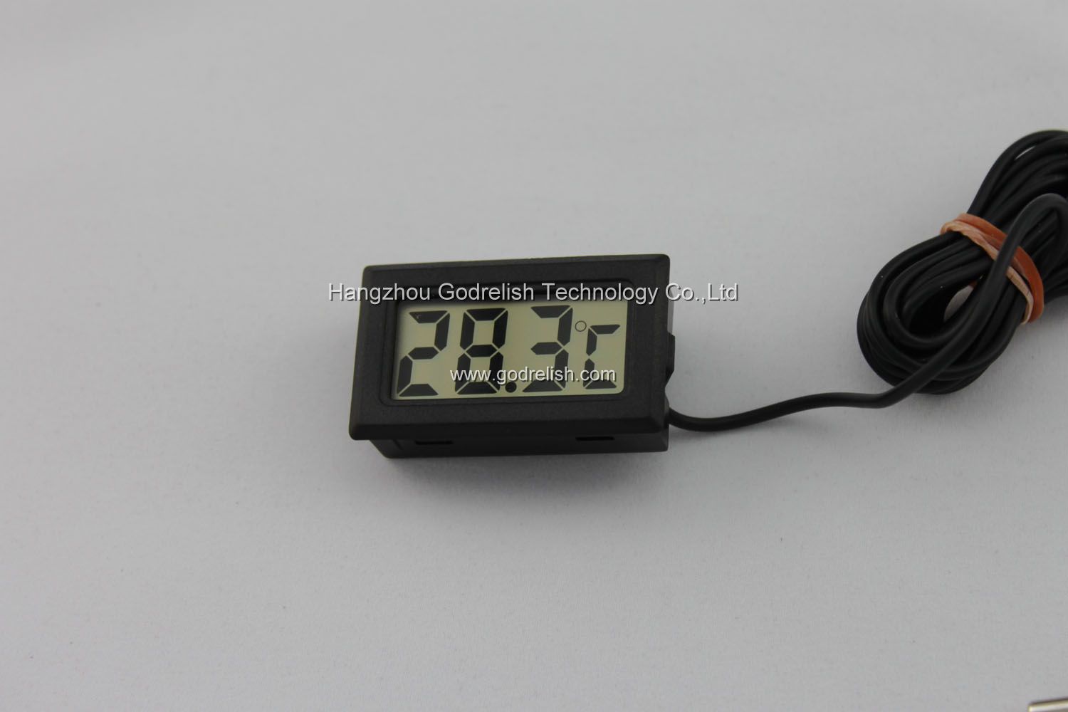
Seven-segment displays can be constructed using any of a number of different technologies. The three most common methods are fluorescent displays (used in many line-powered devices such as microwave ovens and some clocks and clock radios), liquid crystal displays (used in many battery-powered devices such as watches and many digital instruments), and LEDs (used in either line-powered or battery-powered devices). However, fluorescent displays require a fairly high driving voltage to operate, and liquid crystal displays require special treatment that we are not yet ready to discuss. Therefore, we will work with a seven-segment LED display in this experiment.
Schematic Diagram
As shown in the two schematic diagrams above, the LEDs in a seven-segment display are not isolated from each other. Rather, either all of the cathodes, or all of the anodes, are connected together into a common lead, while the other end of each LED is individually available. This means fewer electrical connections to the package, and also allows us to easily enable or disable a particular digit by controlling the common lead. (In some cases, the common connections are made to groups of LEDs, and the external wiring must make the final connections between them. In other cases, the common connection is made available at more than one location for convenience in laying out printed circuit boards. When laying out circuits using such devices, you simply need to take the specific connection details into account.)
There is no automatic advantage of the common-cathode seven-segment unit over the common-anode version, or vice-versa. Each type lends itself to certain applications, configurations, and logic families. We'll learn more about this in later experiments. For the present, we will use a common-cathode display as our experimental example.
皇冠现金网